
The Wrist Zapper, in all her black neoprene beauty...
Intro
Chronic pain is a widespread, but little-understood phenomenon in which the pain of an injury continues after the affected tissue has healed. The Wrist Zapper was developed as part of my undergraduate thesis, and will hopefully play a part in the chronic pain research under way in the Department of Anaesthetics and Perioperative Medicine at Groote Schuur Hospital in Cape Town.
So what is this Wrist Zapper exactly?
The elevator pitch is as follows (I know it sounds hectic - but stick with me!): the Wrist Zapper is a wearable device which continuously measures the extension (up-down) angle of the wearer's wrist, and which shocks them when they enter a specified range of motion. The shock is delivered over the ulnar nerve, just behind the wrist joint, and aims to simulate a fracture of the styloid process. The device is intended to be worn for several weeks, over which time the wearer's behaviour is monitored to see how they adapt to avoid being shocked. The interesting part is to see whether a pain response is conditioned (a la Pavlov's dogs) in the process - i.e. if the intensity of the shock is reduced, does the wearer still report equivalent or similar levels of pain and avoid that range of motion? My role is just the design and testing of the device, not the pain study (I still have no idea how they get ethics clearance for this stuff...).
What's here?
What follows are some photos and videos of the device and its companion app in action, in testing and in normal use. If you're interested to see the code for the project (the tech is two MPU6050 IMUs hooked up to an ESP32, and interfaced to a phone with Blynk via Bluetooth 4.0 / BLE) or build instructions for the device, head over to the git repo. Enjoy!
Contents
(No internal links, sorry :()
1. Final Design
2. Development Process
3. Testing
The Final Design
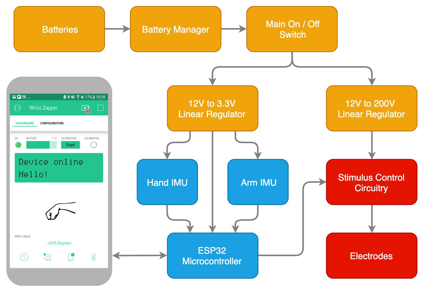
A system-level flow diagram
Hardware
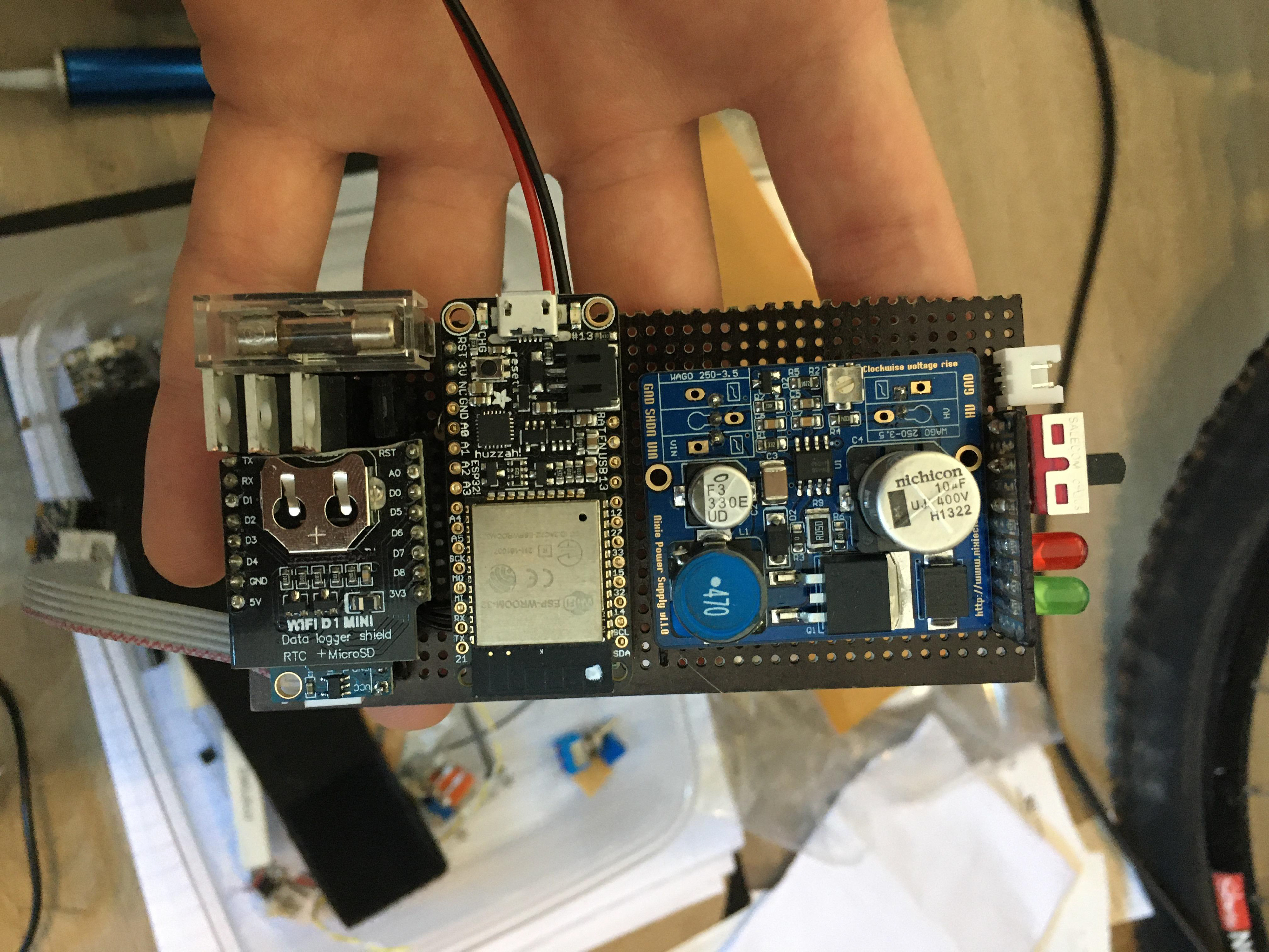
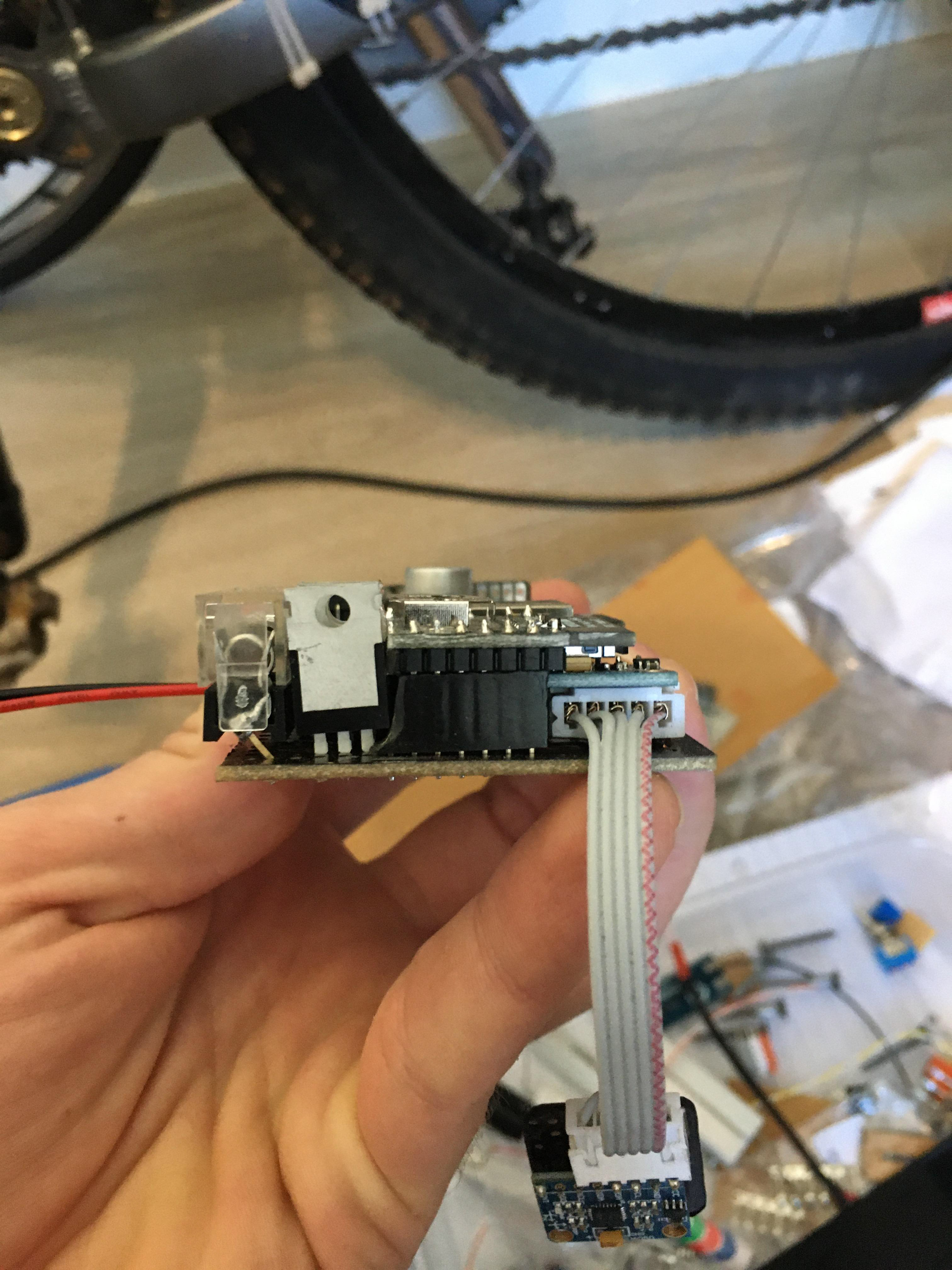
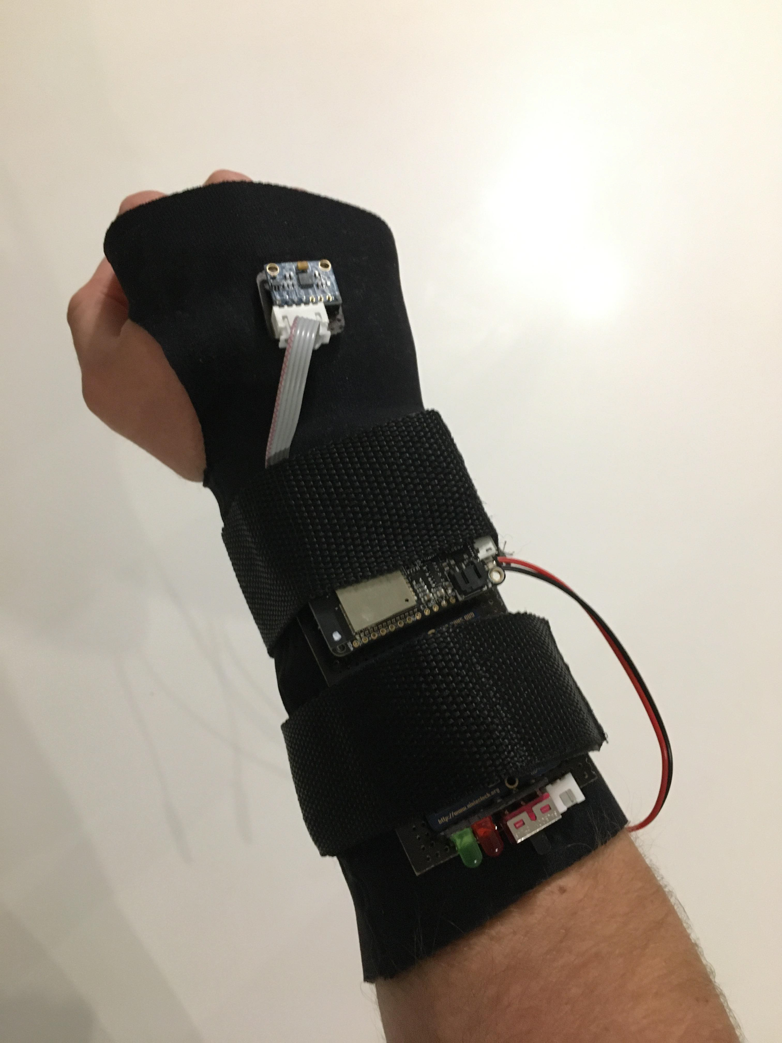
The main elements of the physical design involve a (very squished) circuit board (made on strip board), an electrode (consisting of conductive fencing lamé sewn into elastic fabric), a neoprene sleeve, a charger, and 3D-printed cases for all the electronics.
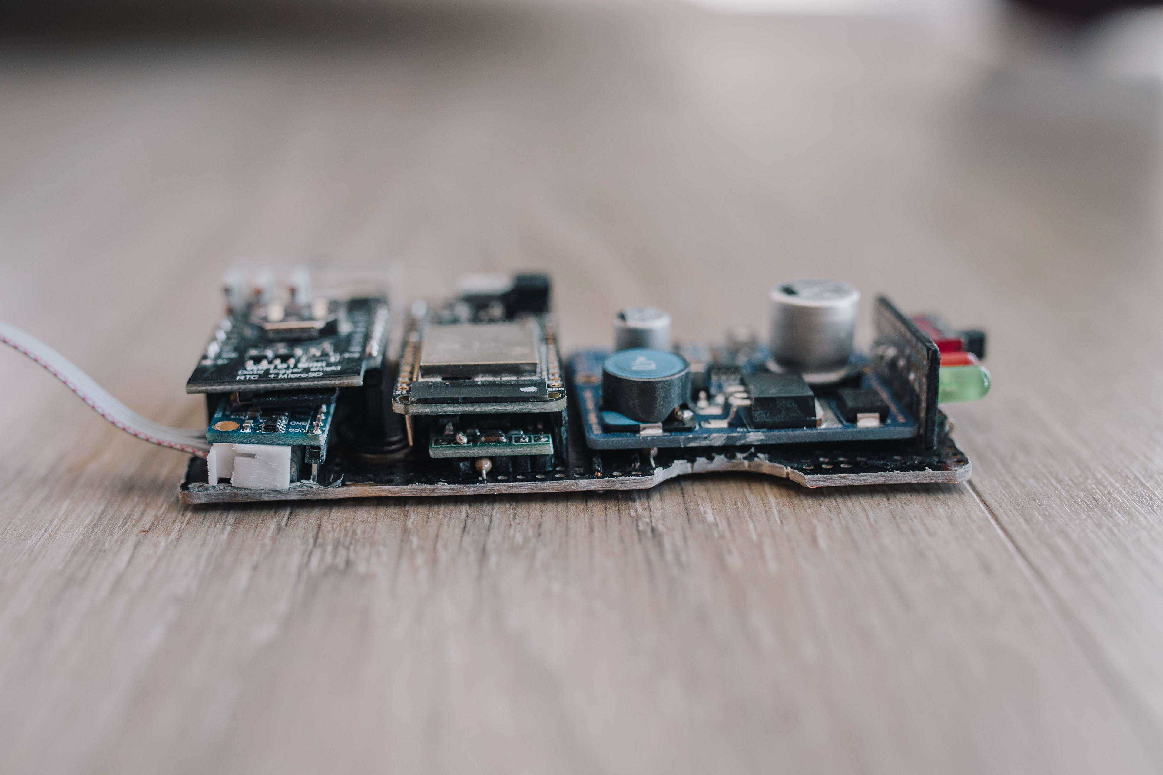
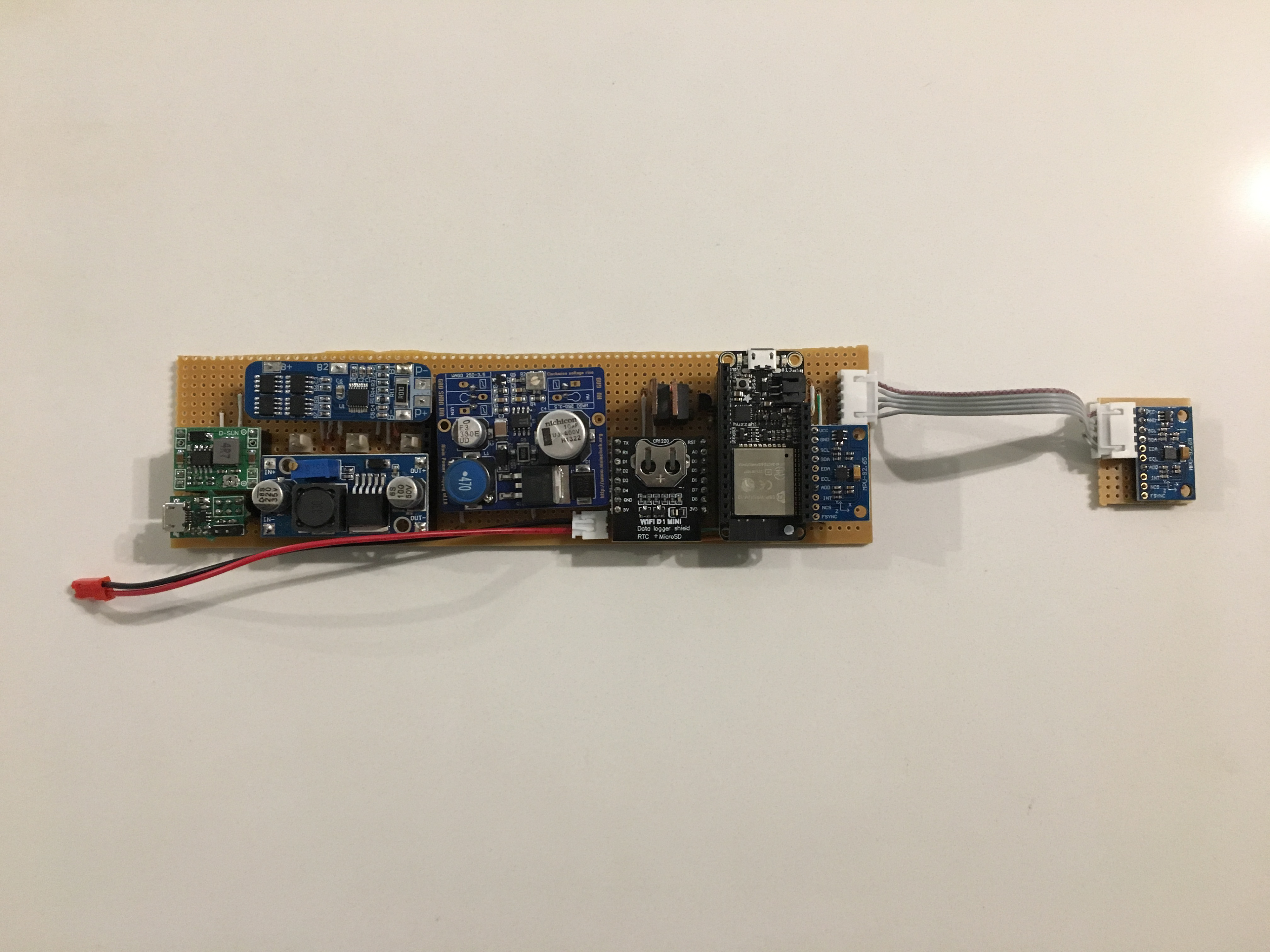
The innards
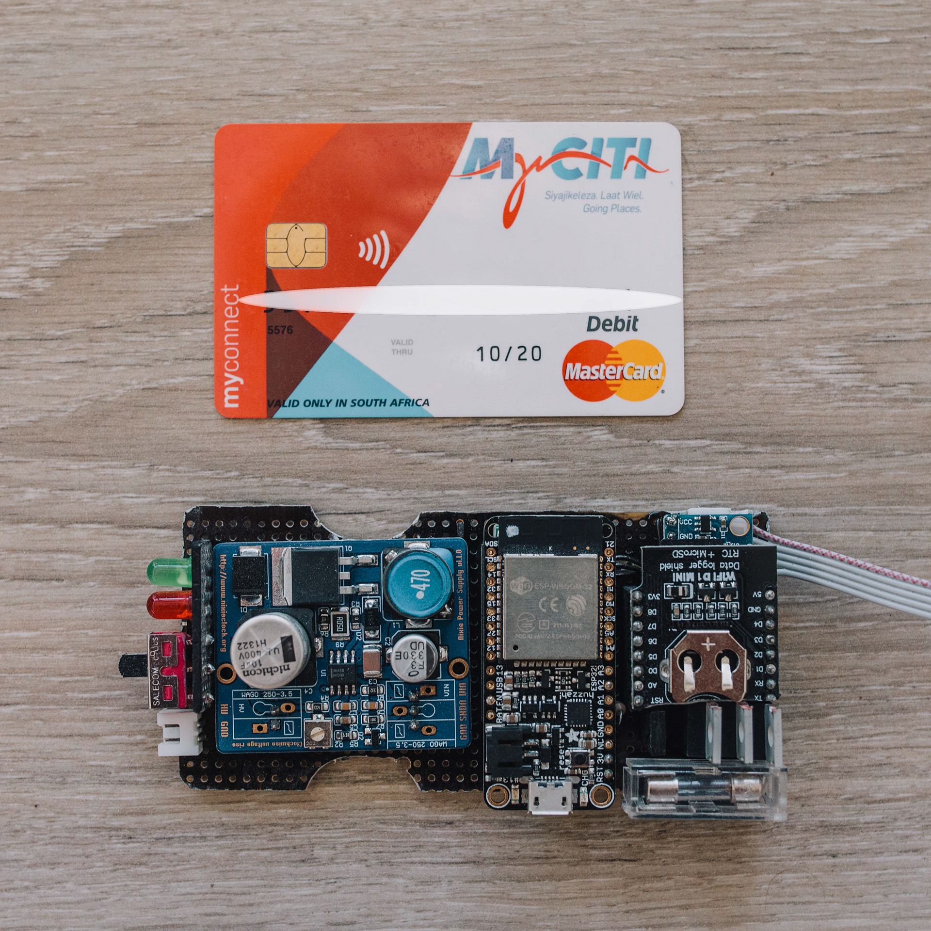
The innards
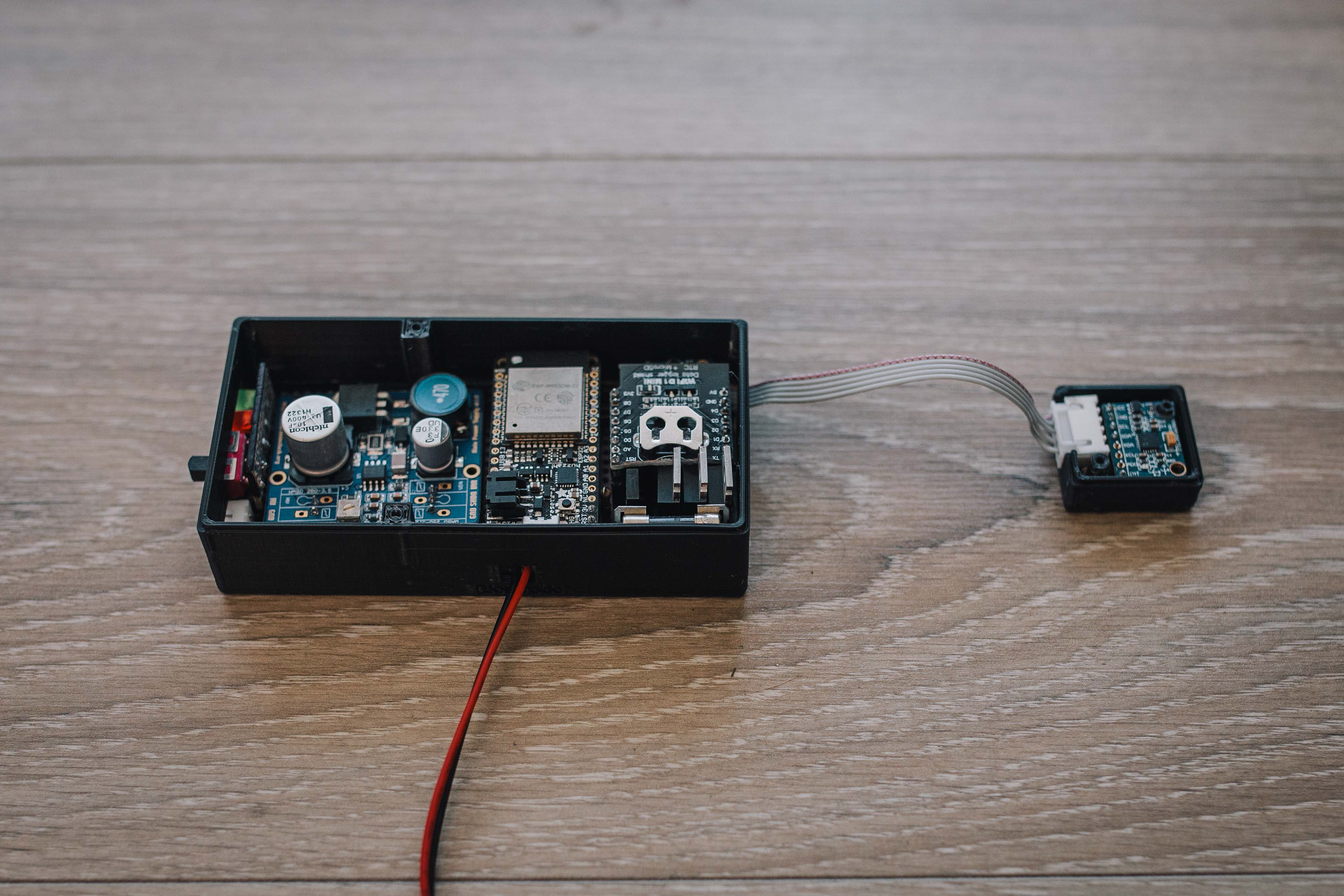
The innards, in their boxes
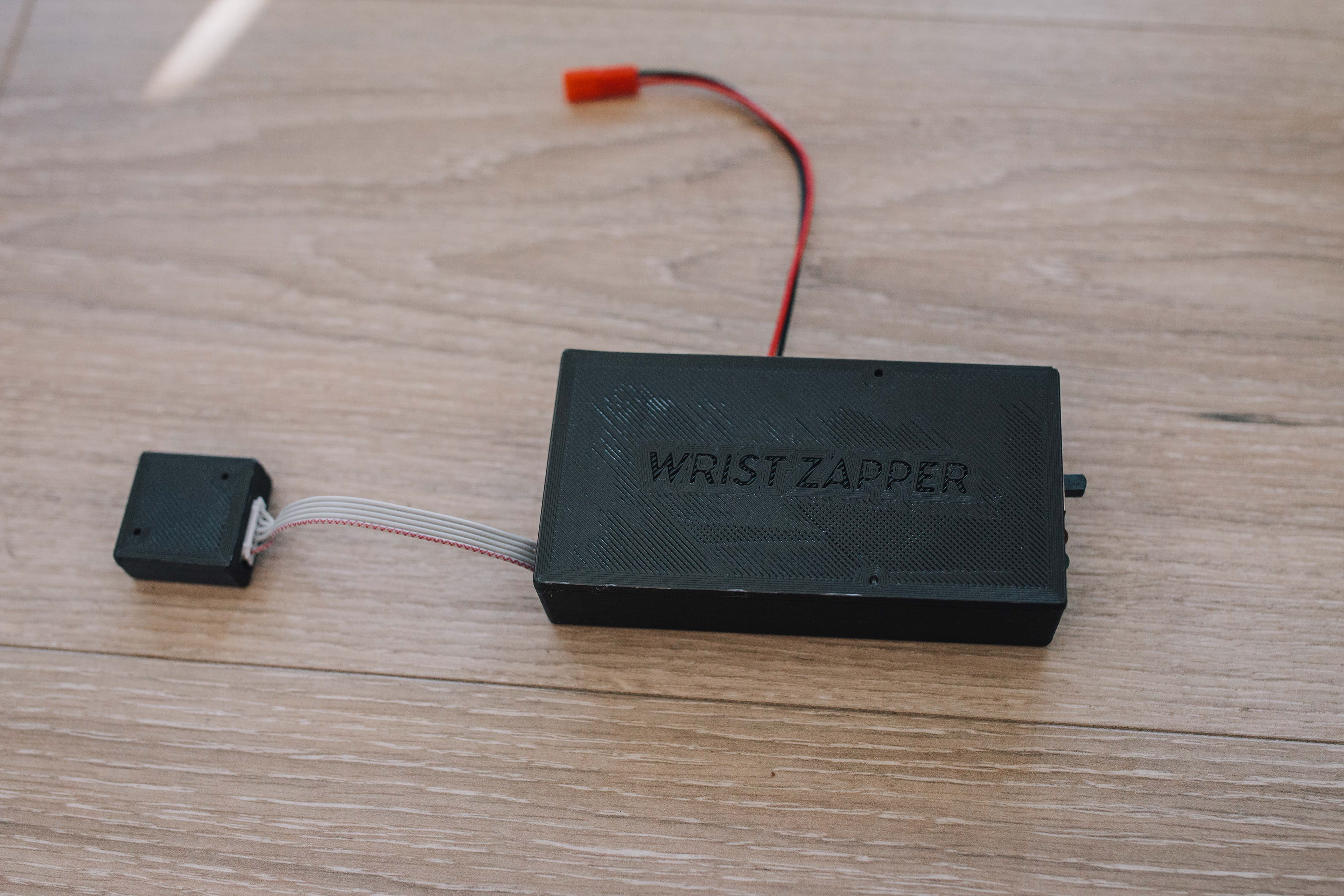
The 3D-printed boxes
The physical interface

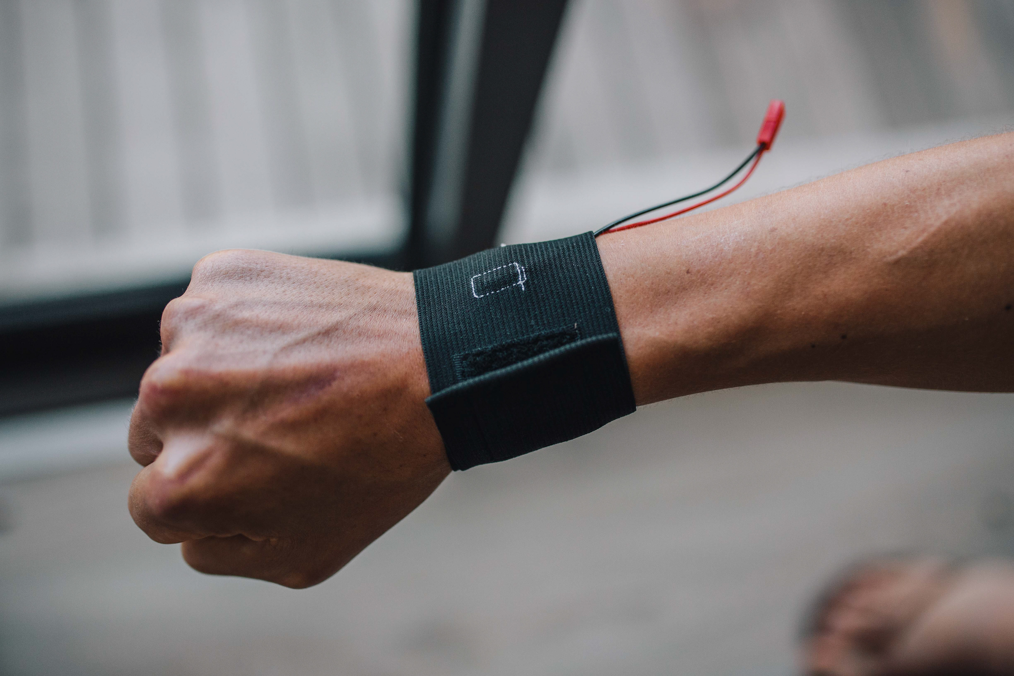
The electrode
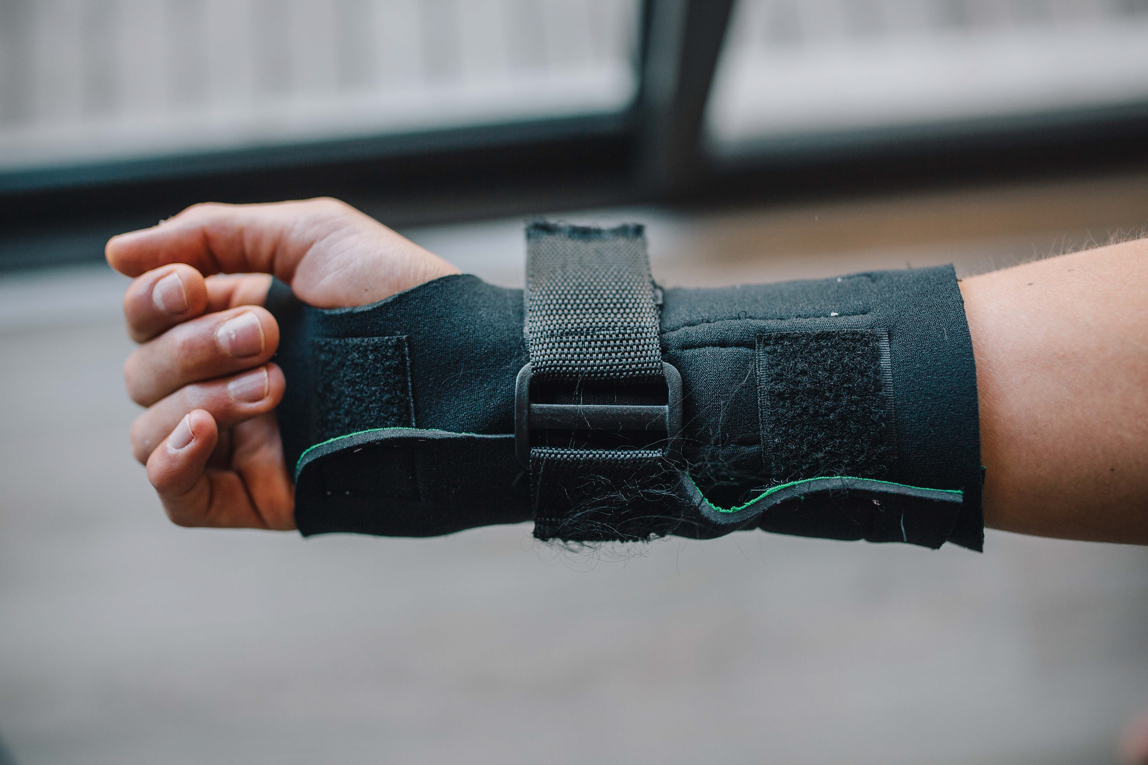
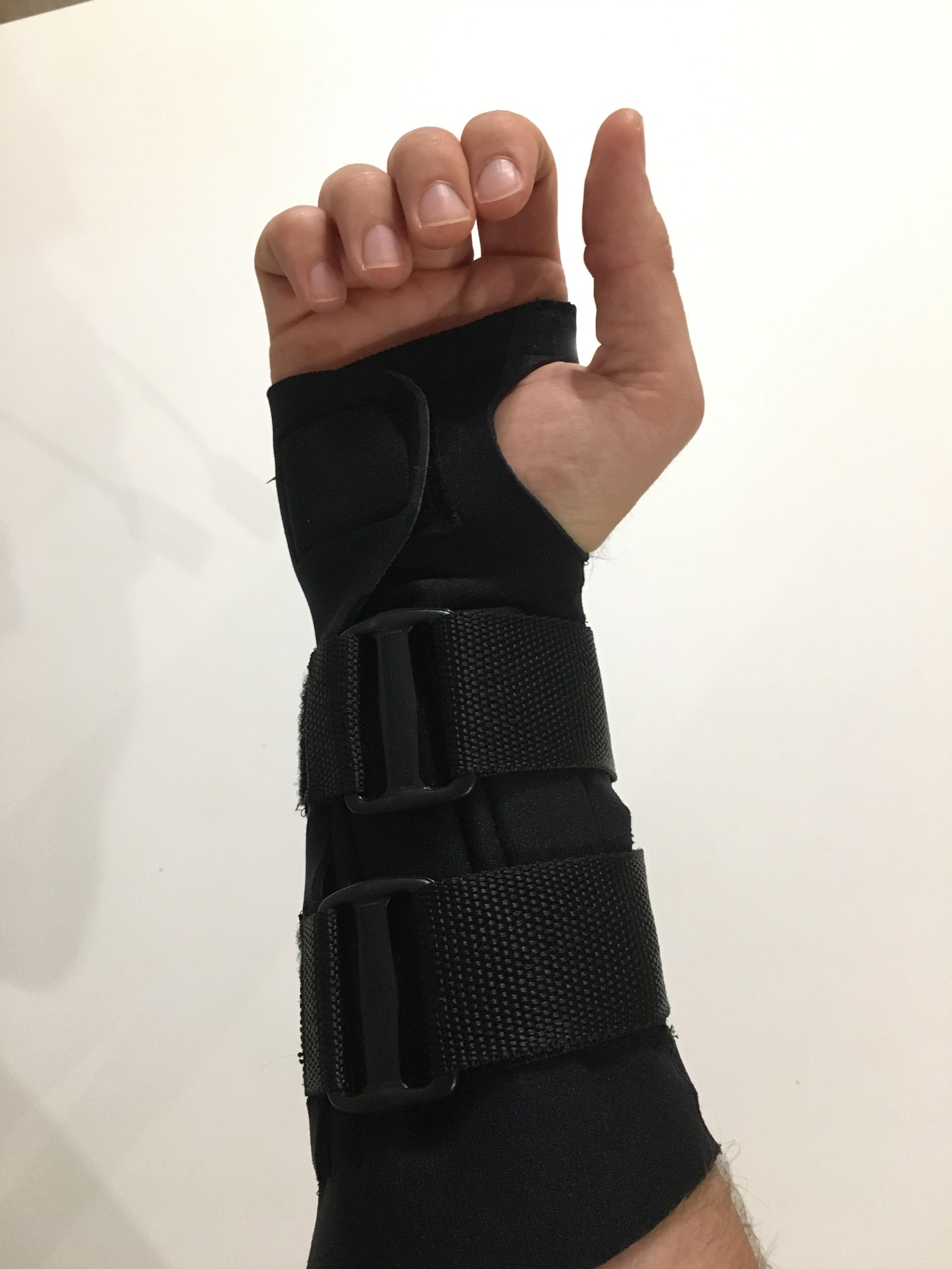
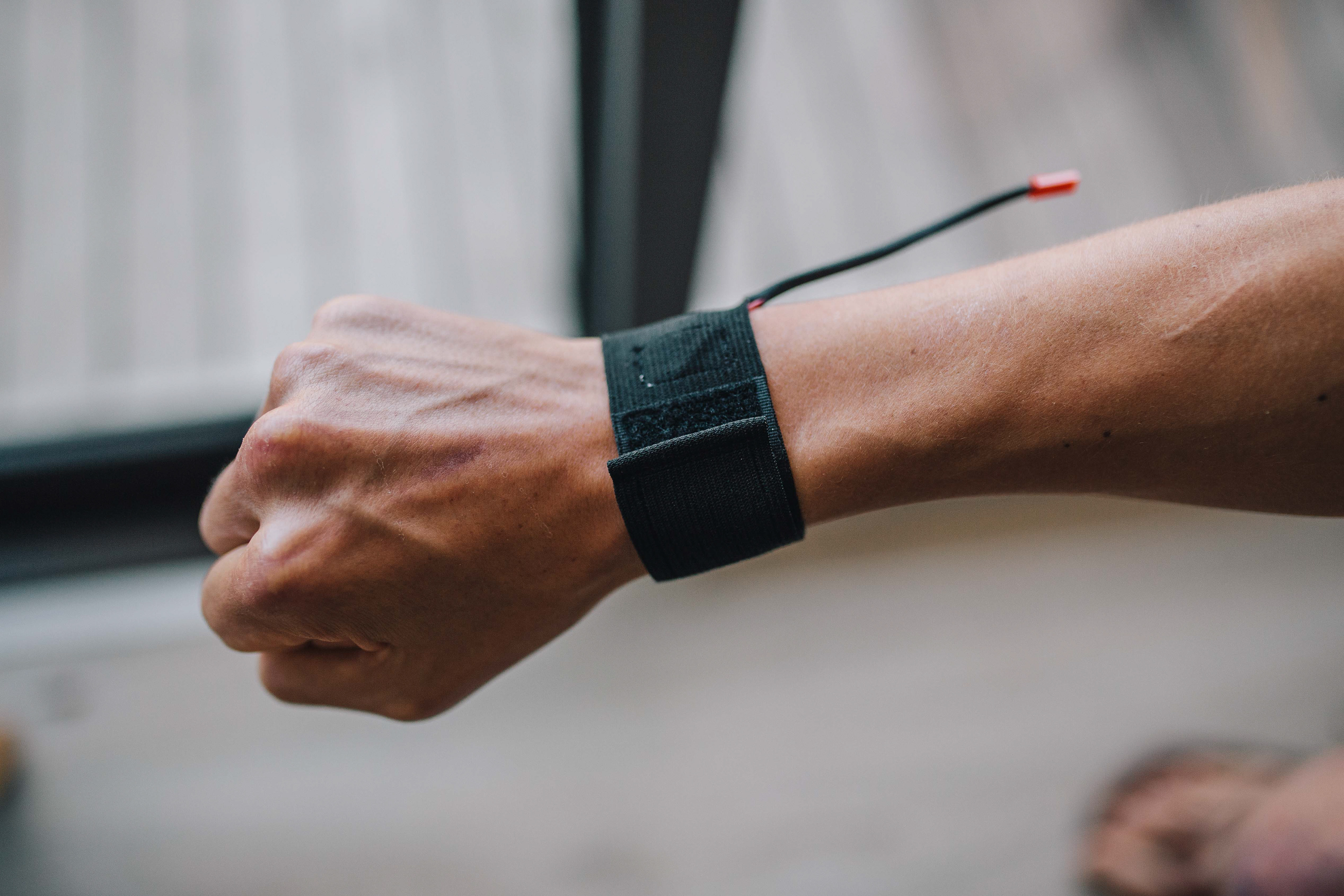
The finished thing!
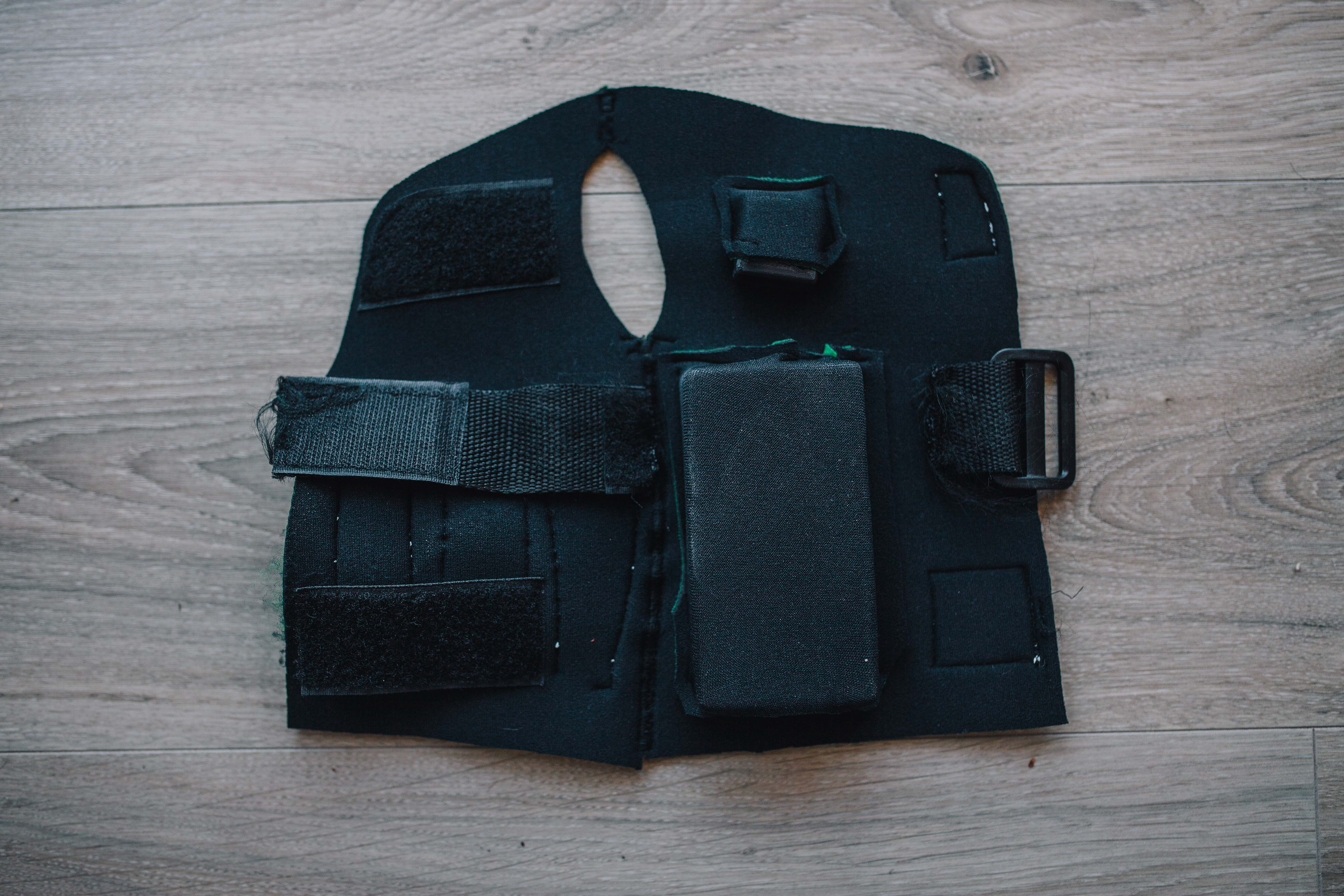
The sleeve and physical interface
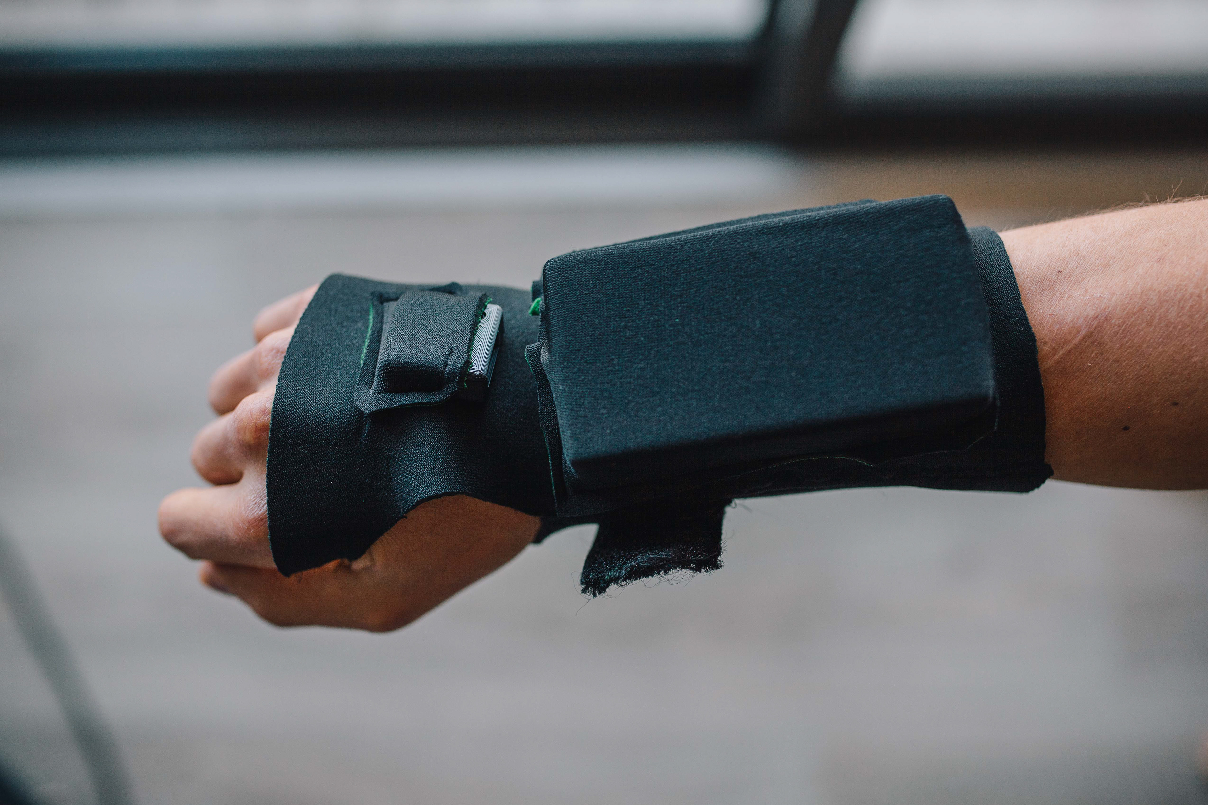
The underside
The charger
Electronics
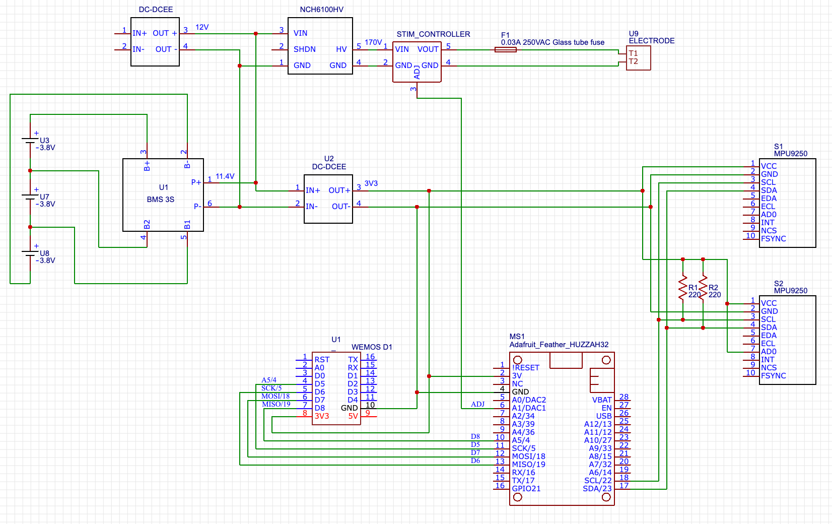
Complete circuit diagram
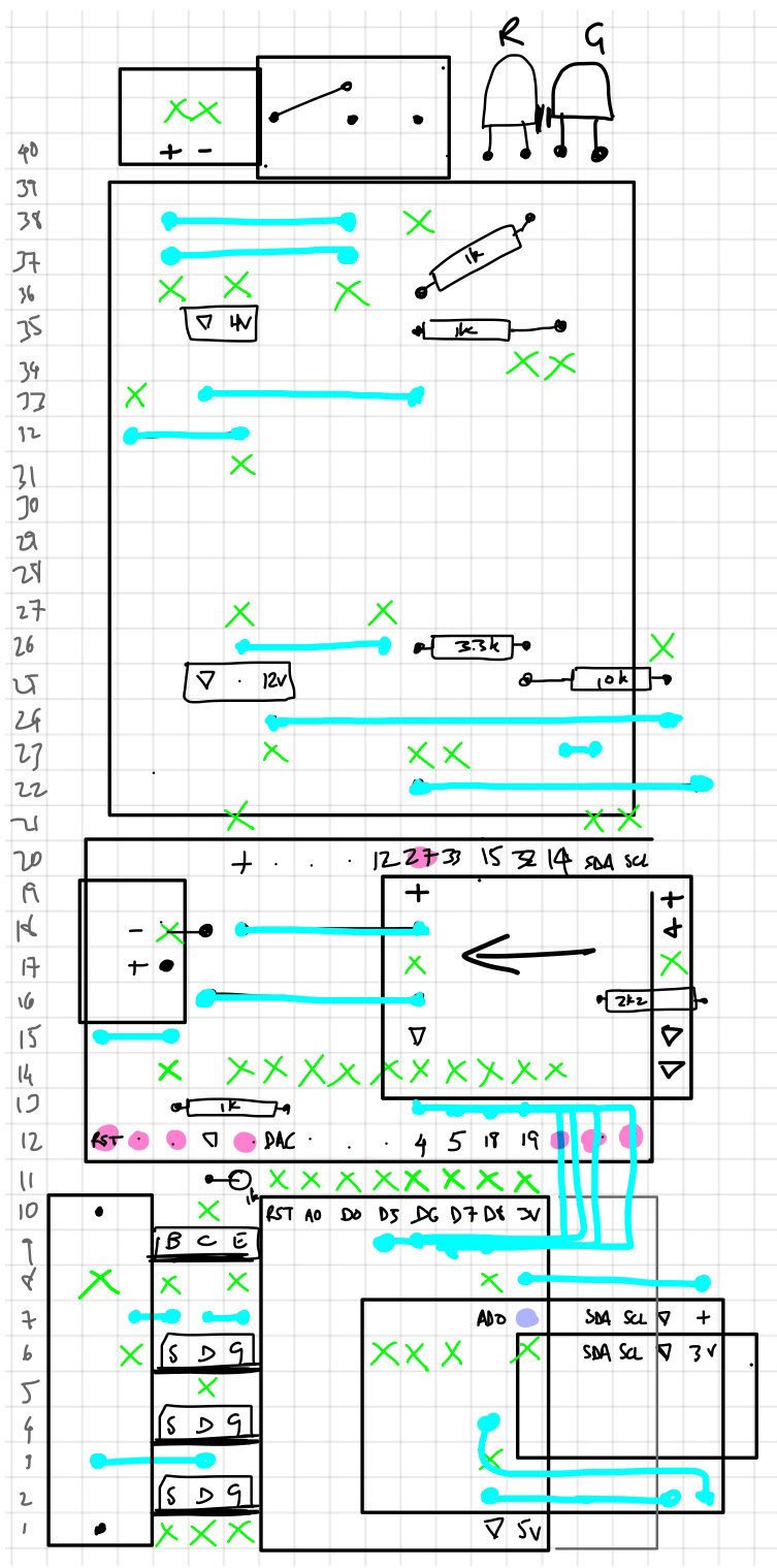
Main board layout
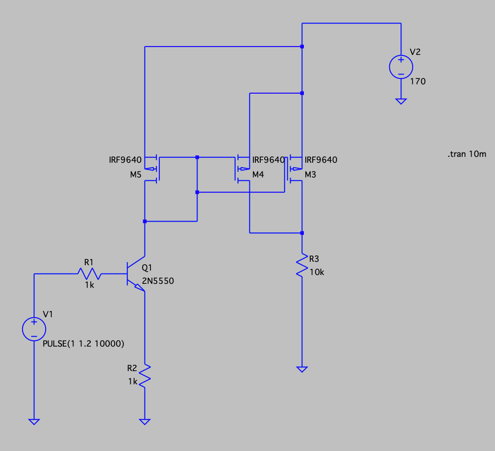
Stimulus controller circuit
Software
There is a lot of code required to keep the brains of the device (an ESP32 microcontroller) doing what it should and relaying what it measures to a phone. This section is focussed on the companion application with which a wearer or clinician would talk to the device. Below are several screenshots of the app in various scenarios.
Main screen. Connection successful
Main screen. Issue with IMU connections
Configuration screen, with different options for reports and stimulus start and maximum angles and intensities
Changing the angle alters the picture too
Vertical calibration, position incorrect
Horizontal calibration, position incorrect
Horizontal calibration, position correct, calibration running
Calibration complete
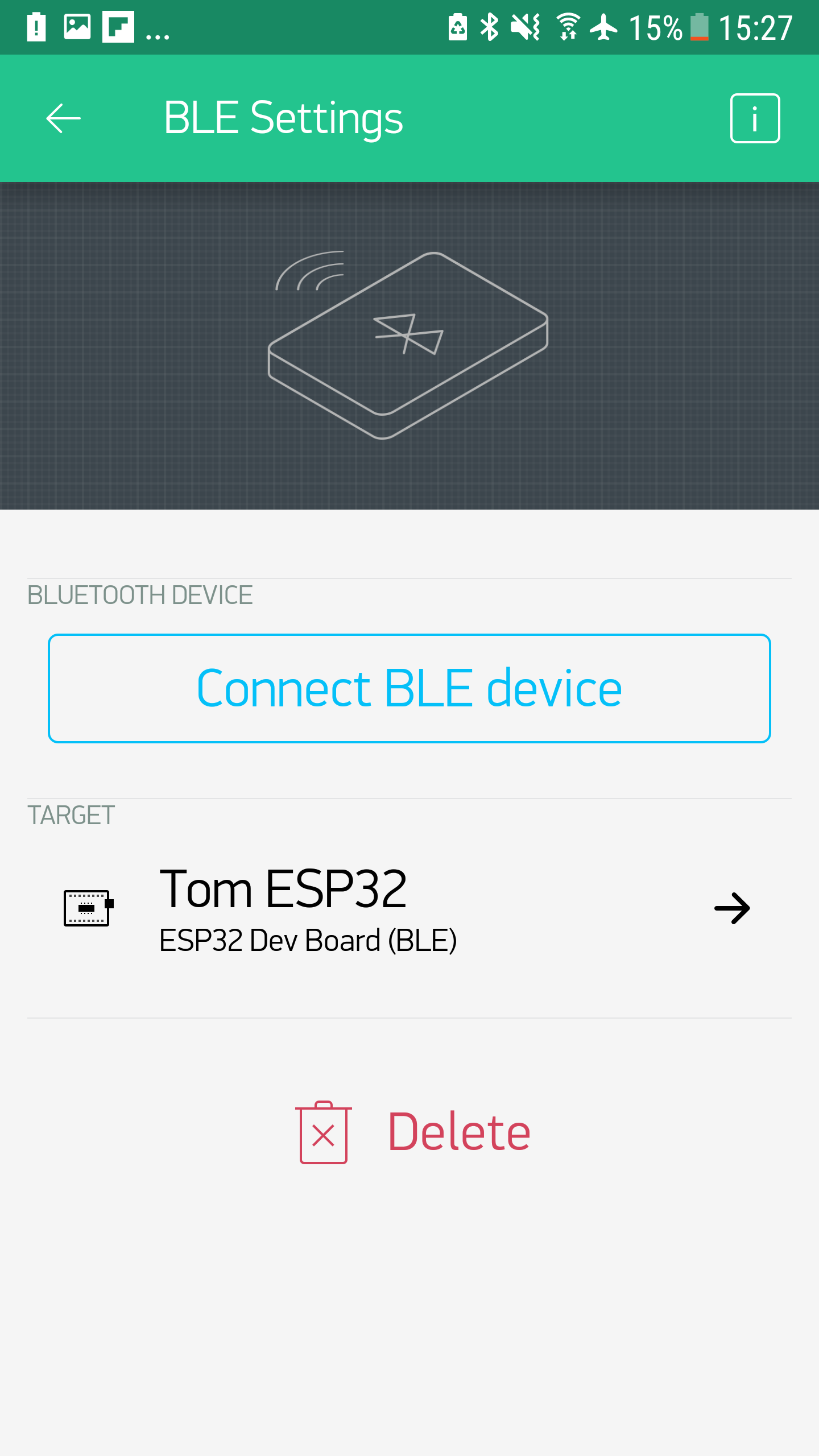
Connecting via BLE
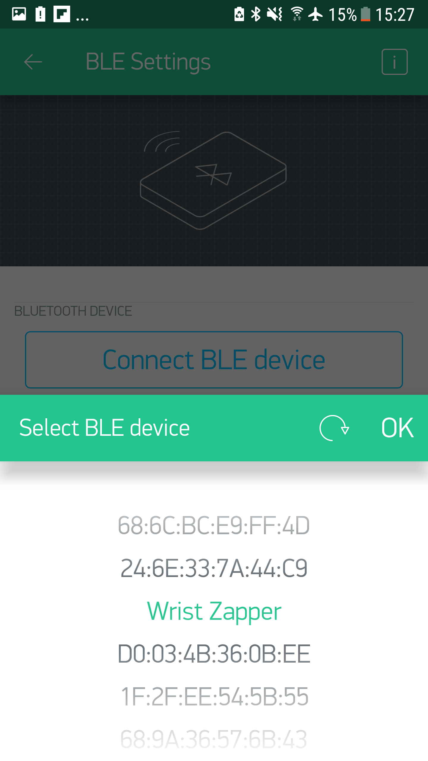
Pick the Wrist Zapper!
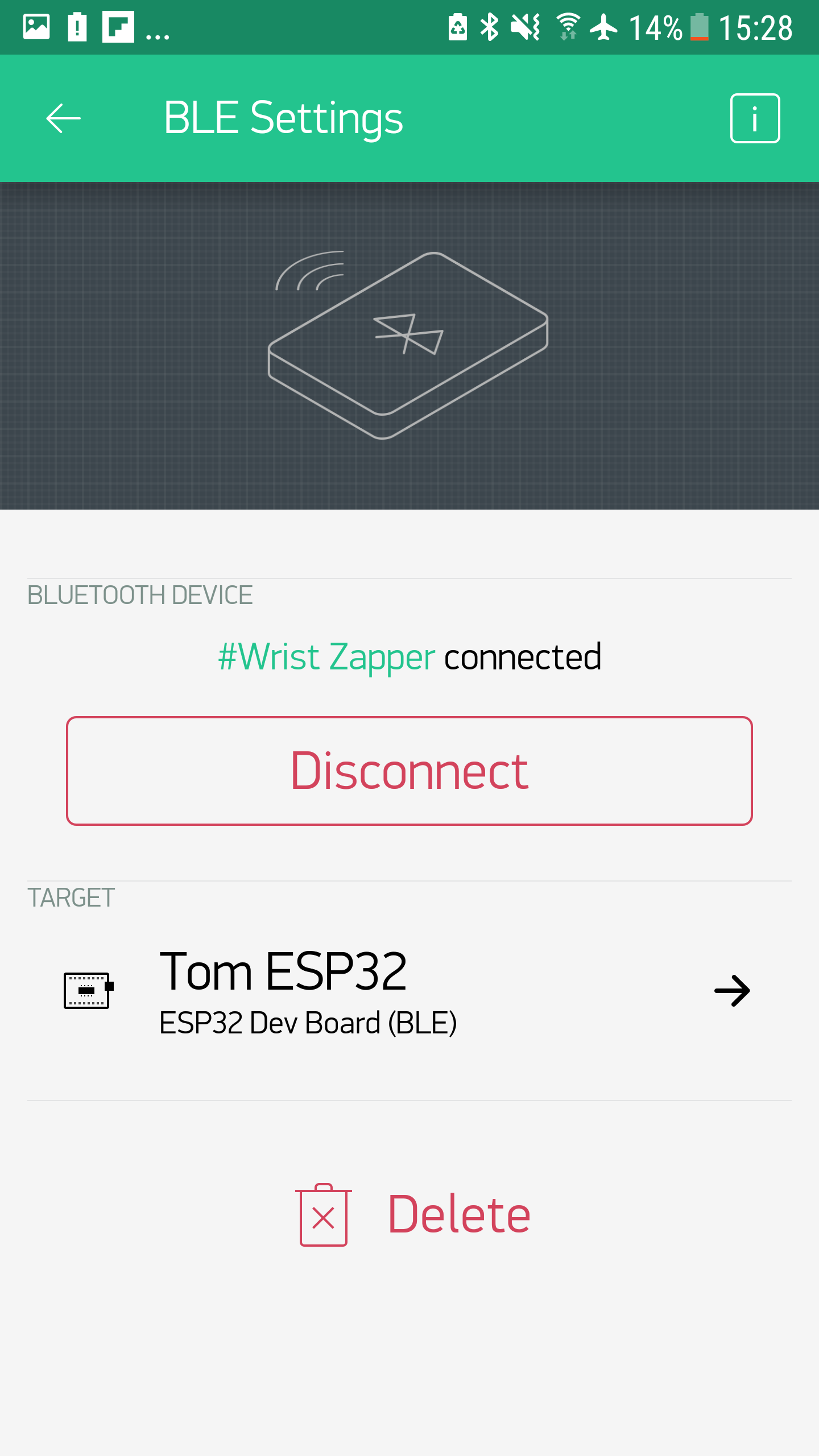
And we're good to fly
The app guides the user through the calibration routine. The process involves the user holding their arm vertically downward, and then horizontally. Feedback is given by an on-screen indicator, as well as using the LEDs on the back of the device to indicate whether the user is in an acceptable range (to prevent confounding). The device waits until the arm is well-posed before going ahead with calibration. The video below shows the process live.
Development
Most parts of the design had more than one prototype iteration involved on the way to their current forms. The final version of the neoprene sleeve was prototype 11! The story of those nightlies is briefly catalogued below.
The Circuit Board
All together for the first time

Mapping board planning to hardware
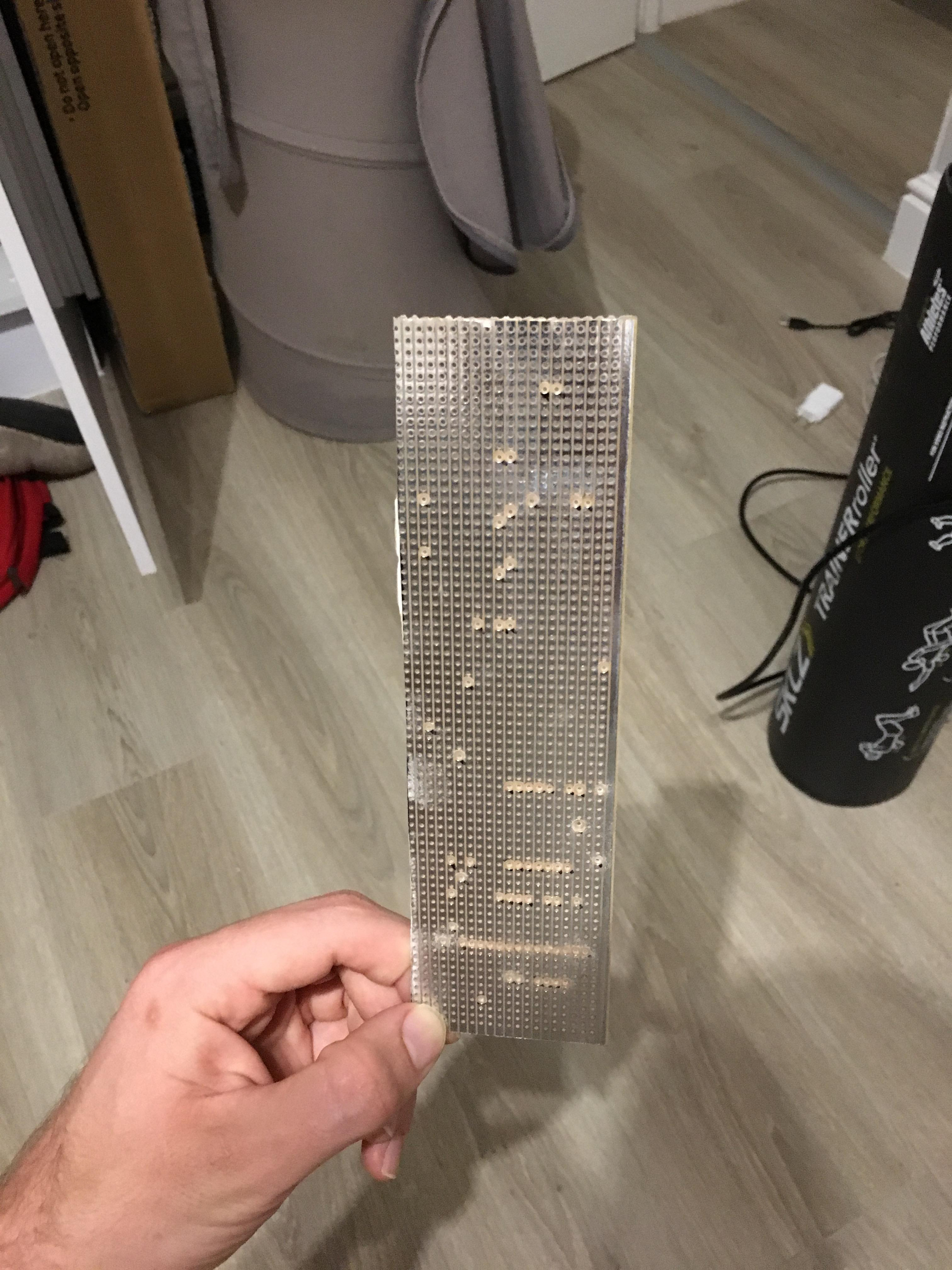
Board prepped
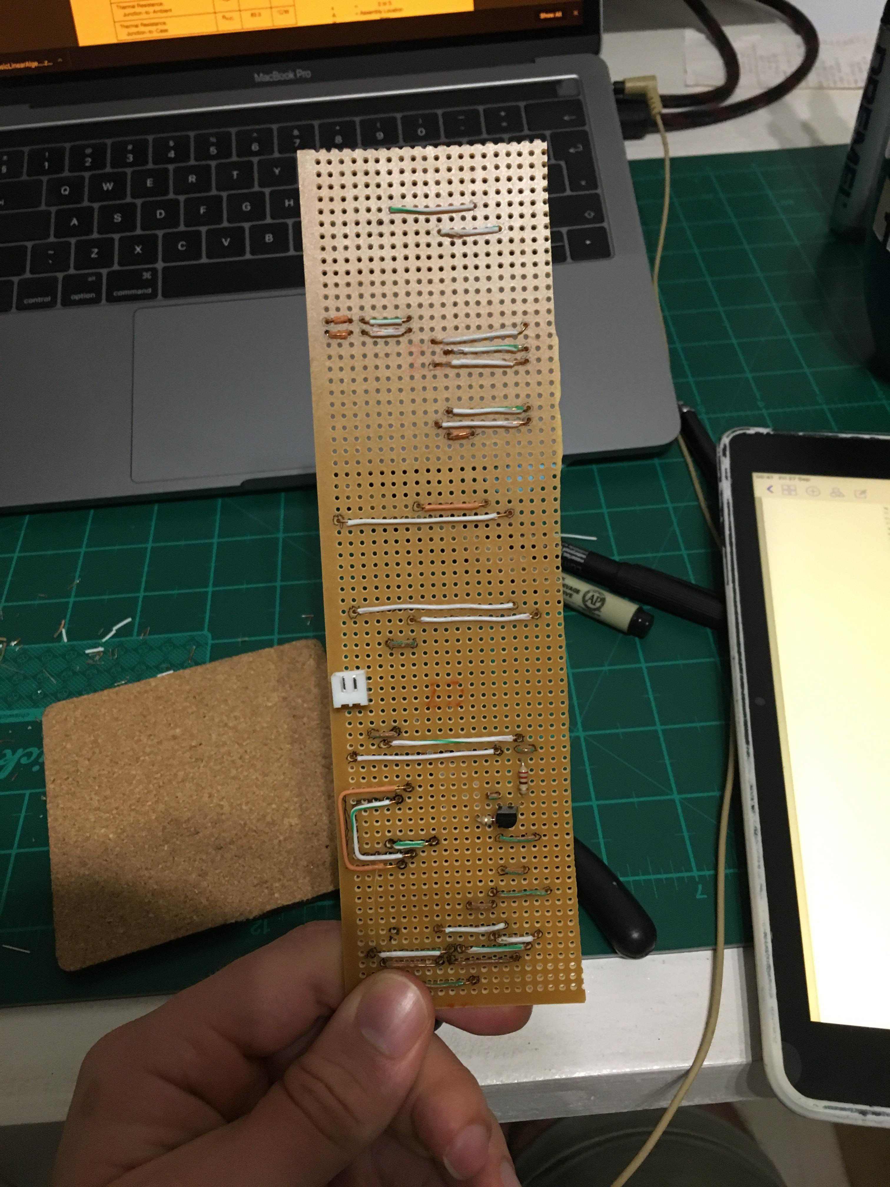
The undergrowth
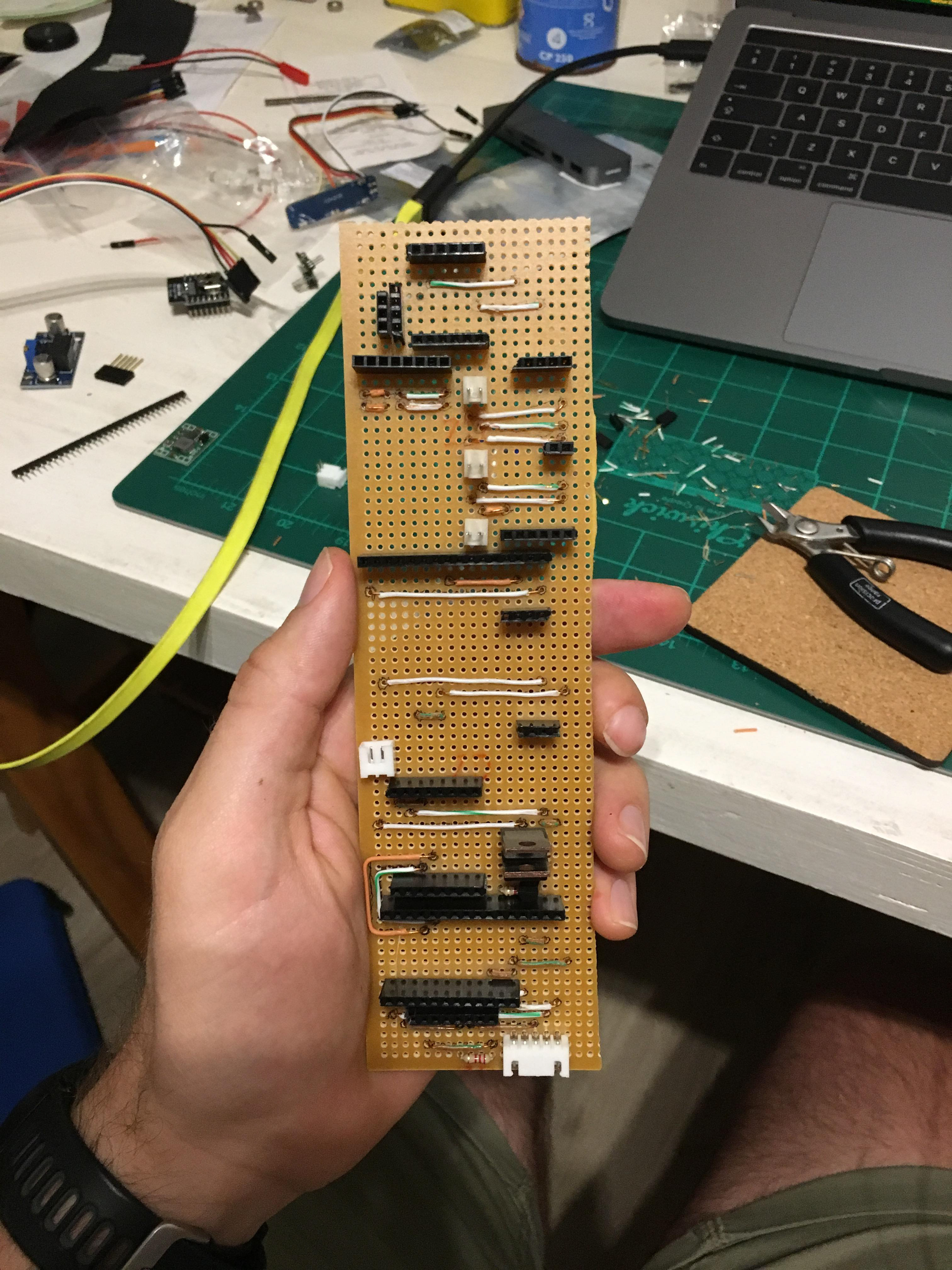
The middle canopy
The whole toot
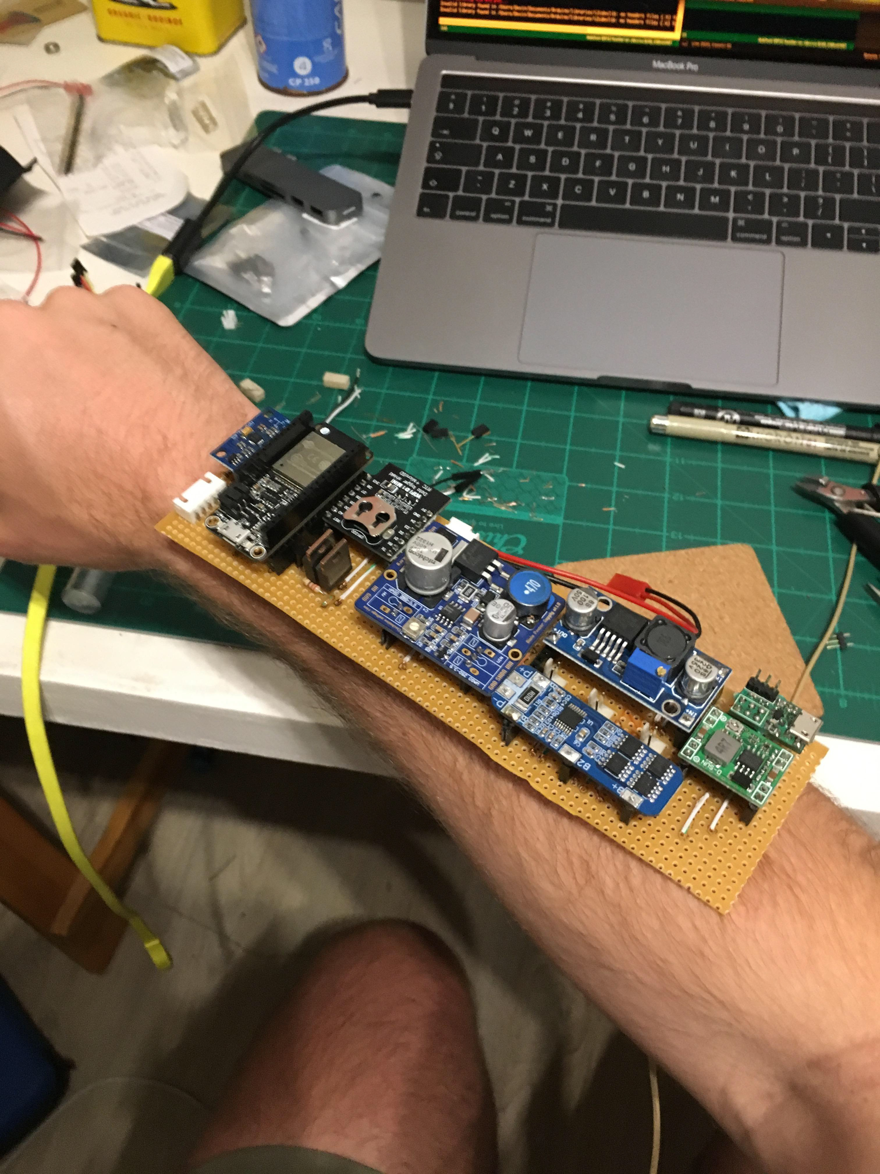
Shucks she's a whopper!
A cheeky flattened pin causing hassles
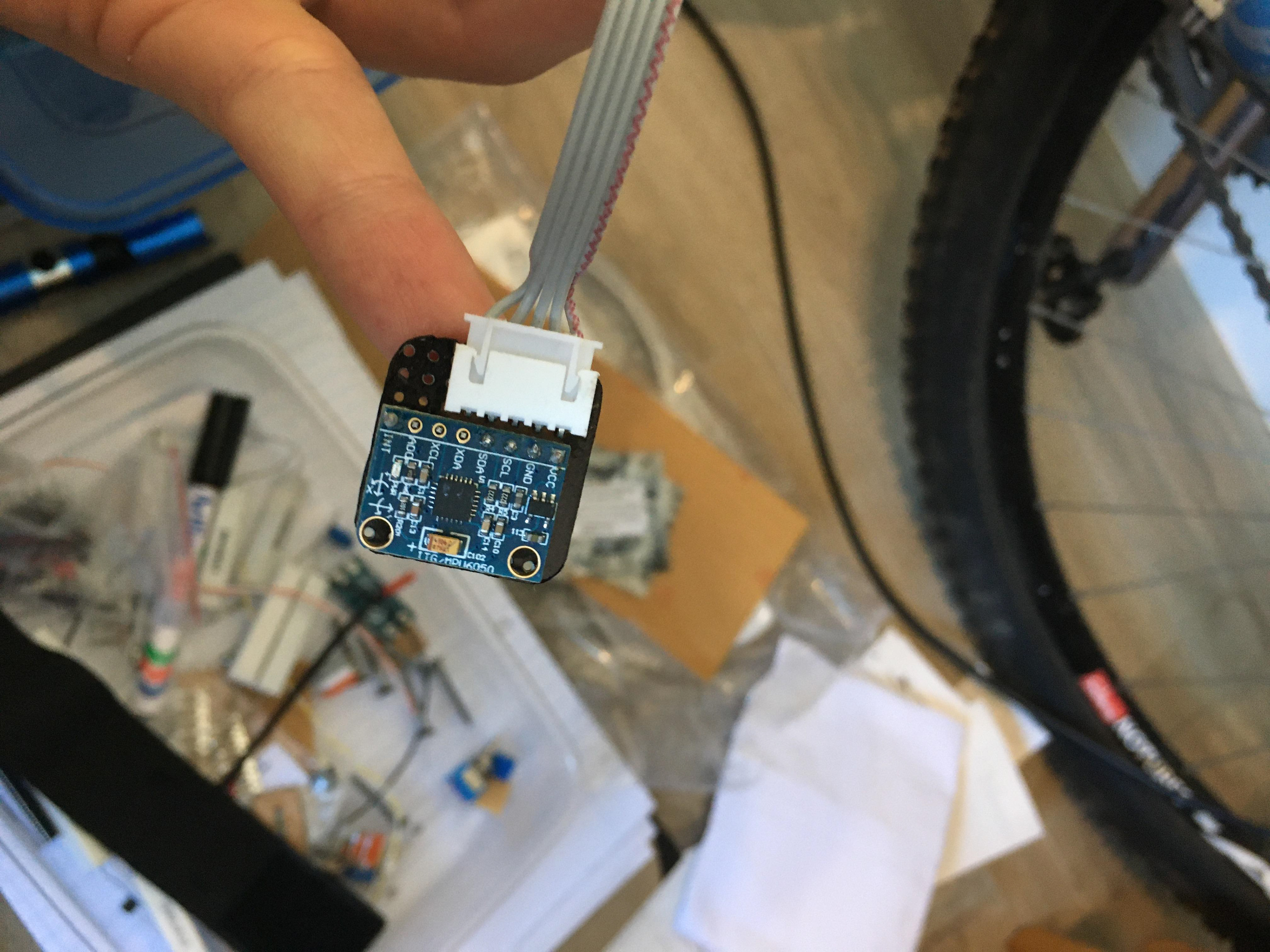
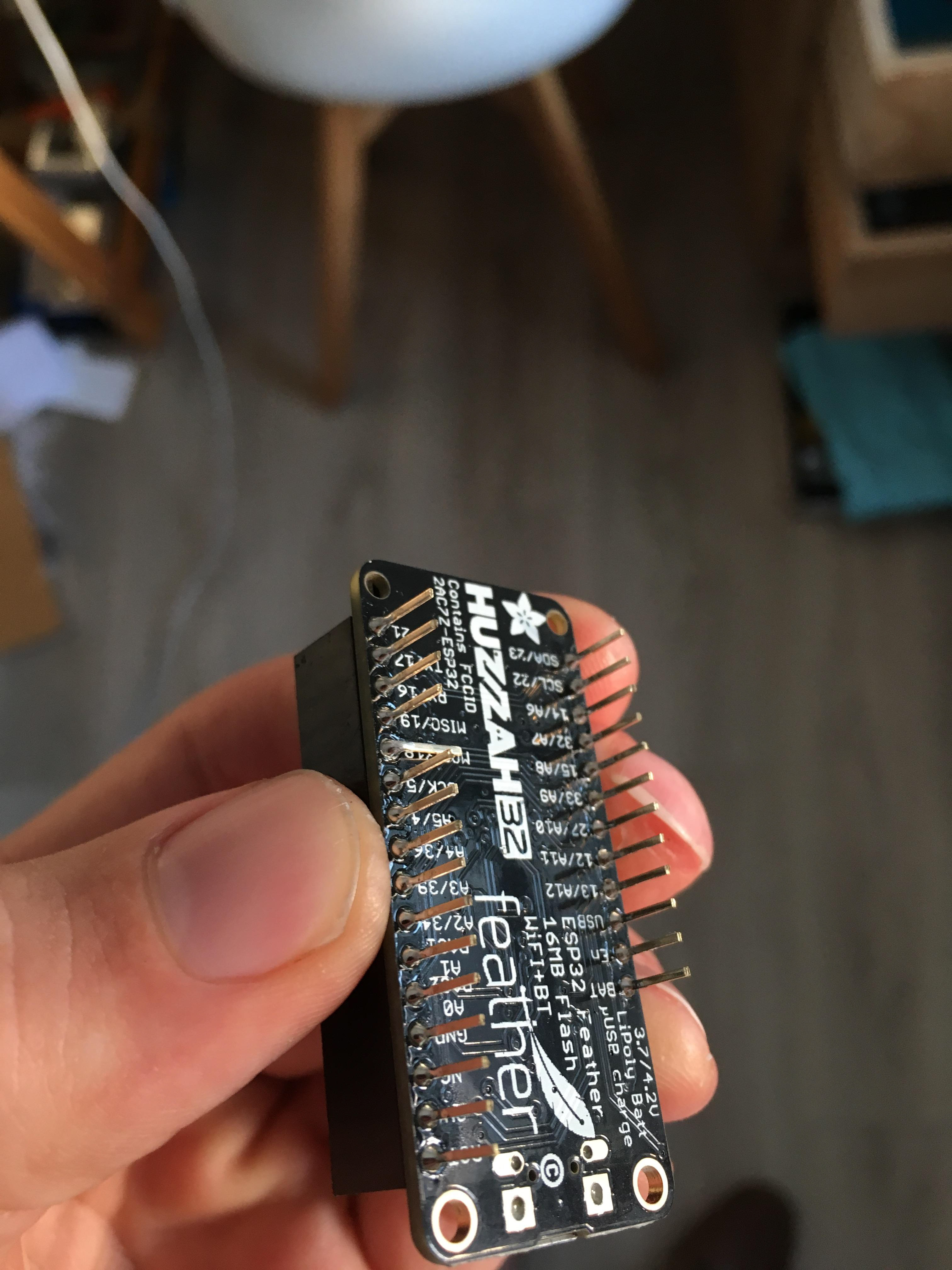
Hand IMU breakout done
Major stacking going on
New board soldered and working!
Front view
Design for arm circuit enclosure
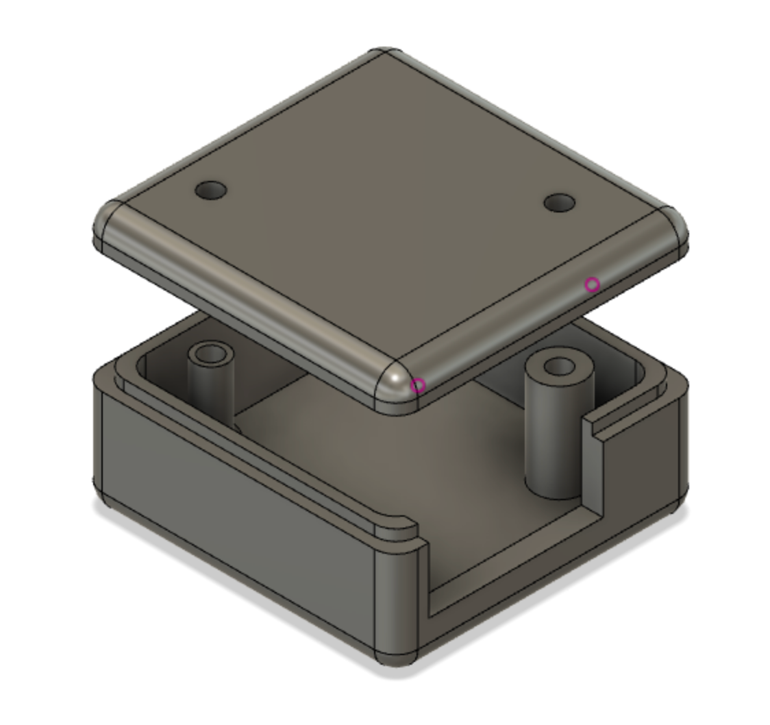
Design for hand circuit enclosure
The Sleeve
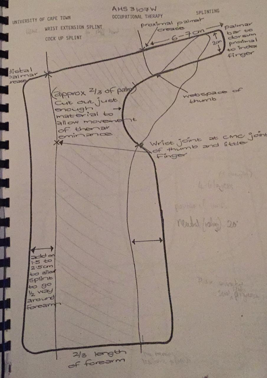
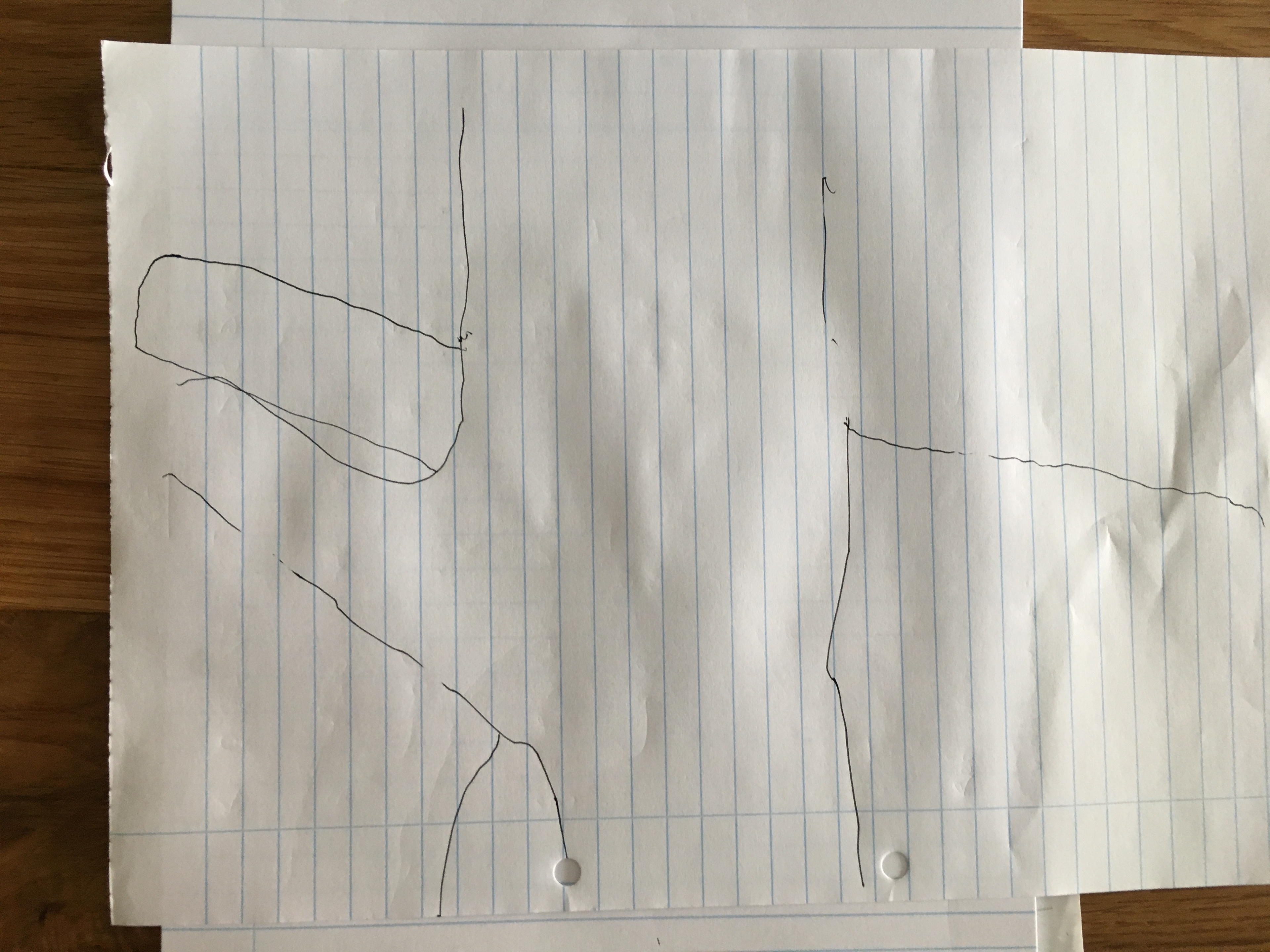
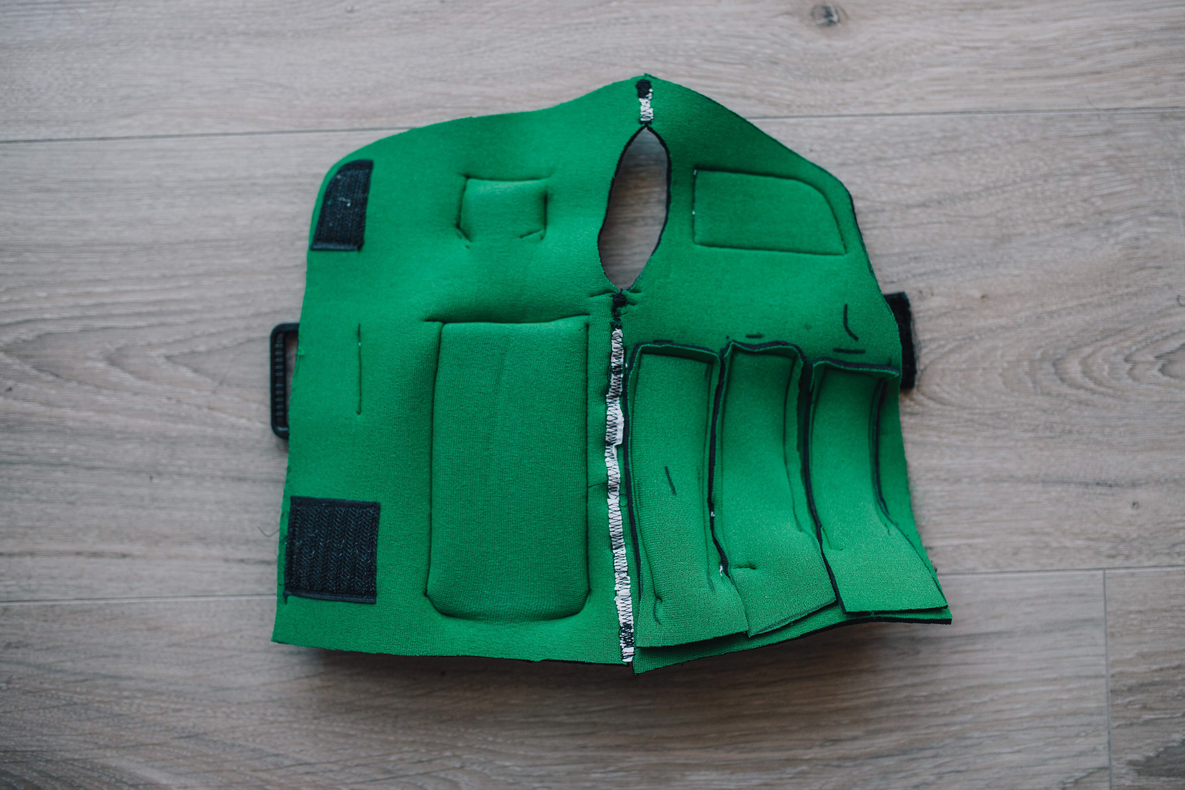
The sleeve started out as a paper model based on a design from some occupational therapist friends of mine. I had intended to use compression stocking material, but the OTs suggested I rather try neoprene. On a whim I paid a visit to the Coral wetsuit factory in Salt River, and the folks there were very generous to give me a stack of offcuts. I used almost every inch!
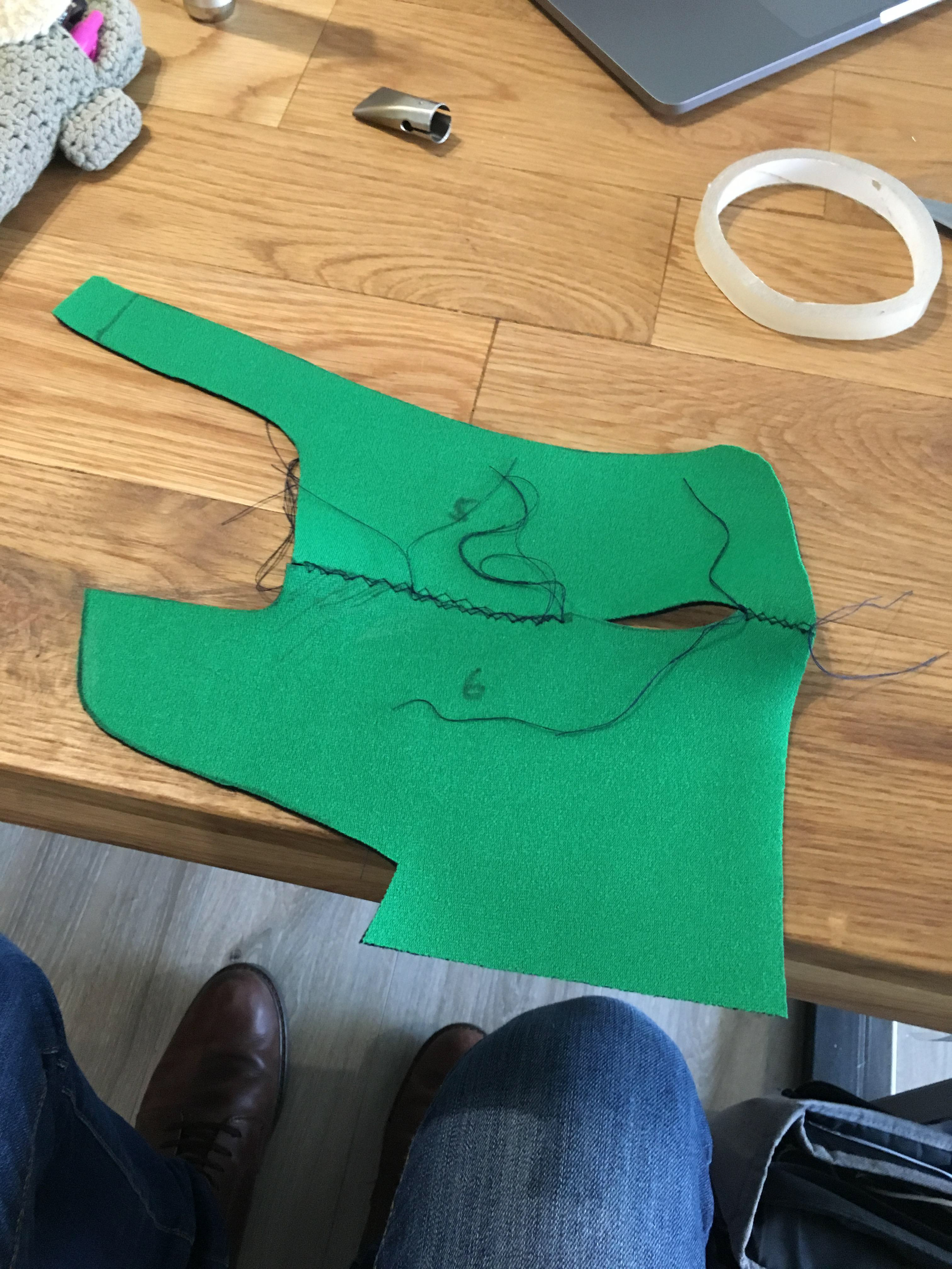
The first half were all made with separate pieces for the hand and forearm portions. The biggest turning point in the design was when I handed a few of my early neoprene models to my sister to test, and she instinctively put her thumb through the hole I'd made to go behind the wrist to maximise flexibility and prevent bunching. There was no looking back, and the rest all featured the thumb hole with a lengthwise seam.
Genesis
Making it my own
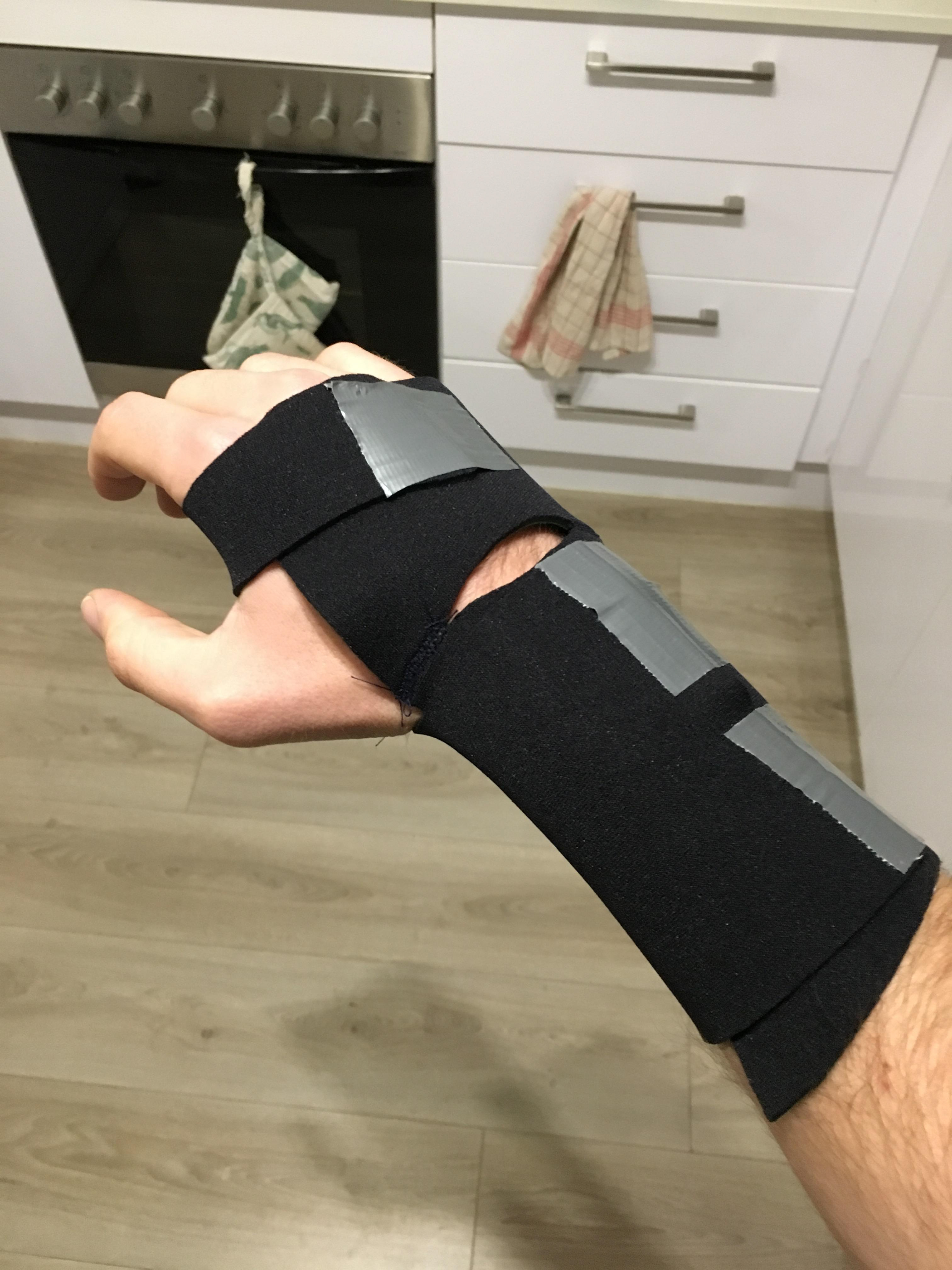
Paper to neoprene (and an unhappy sewing machine...)
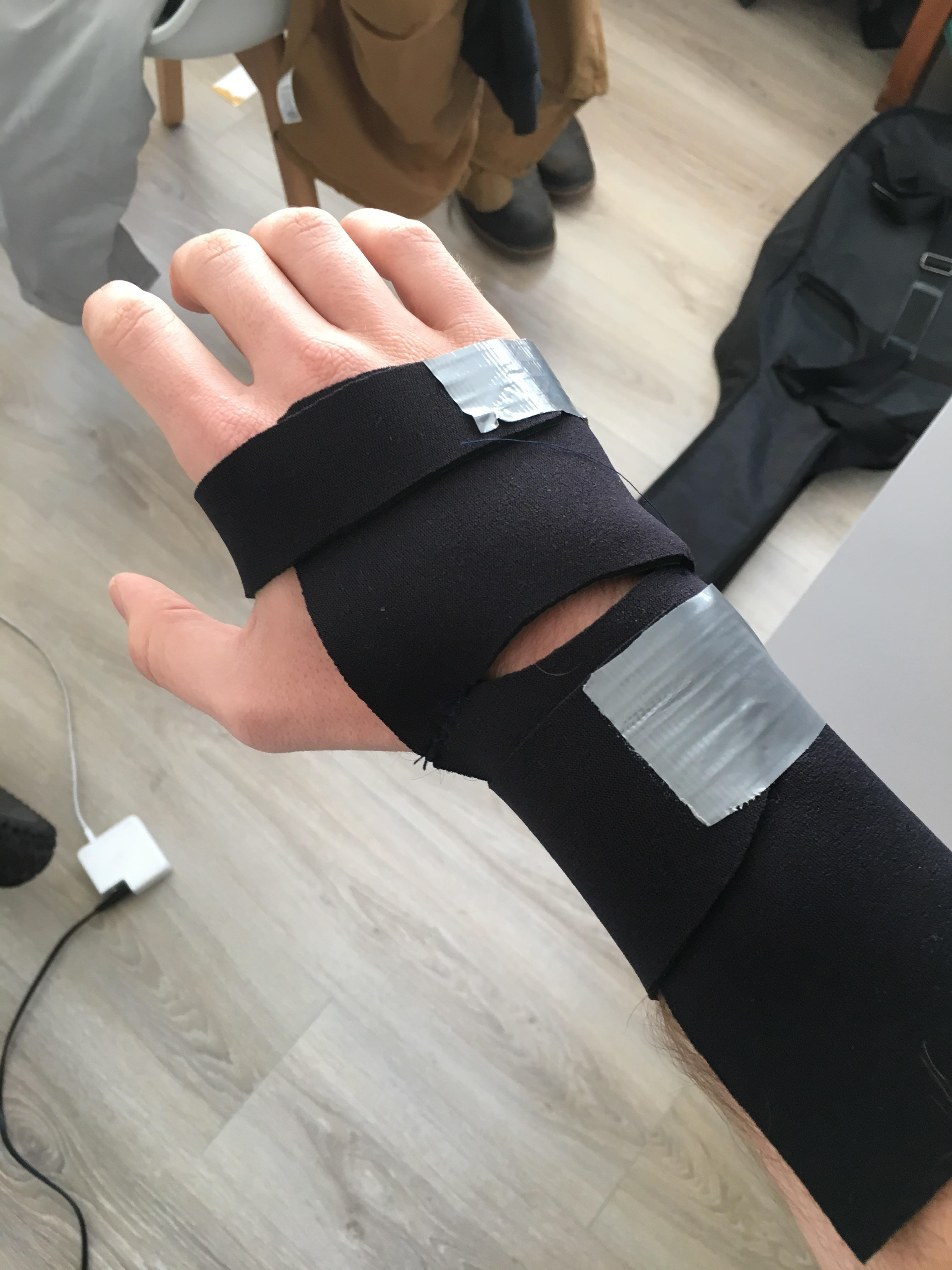
#Protip, ducktape makes a great velcro replacement
The fateful thum hole on that second neoprene version.
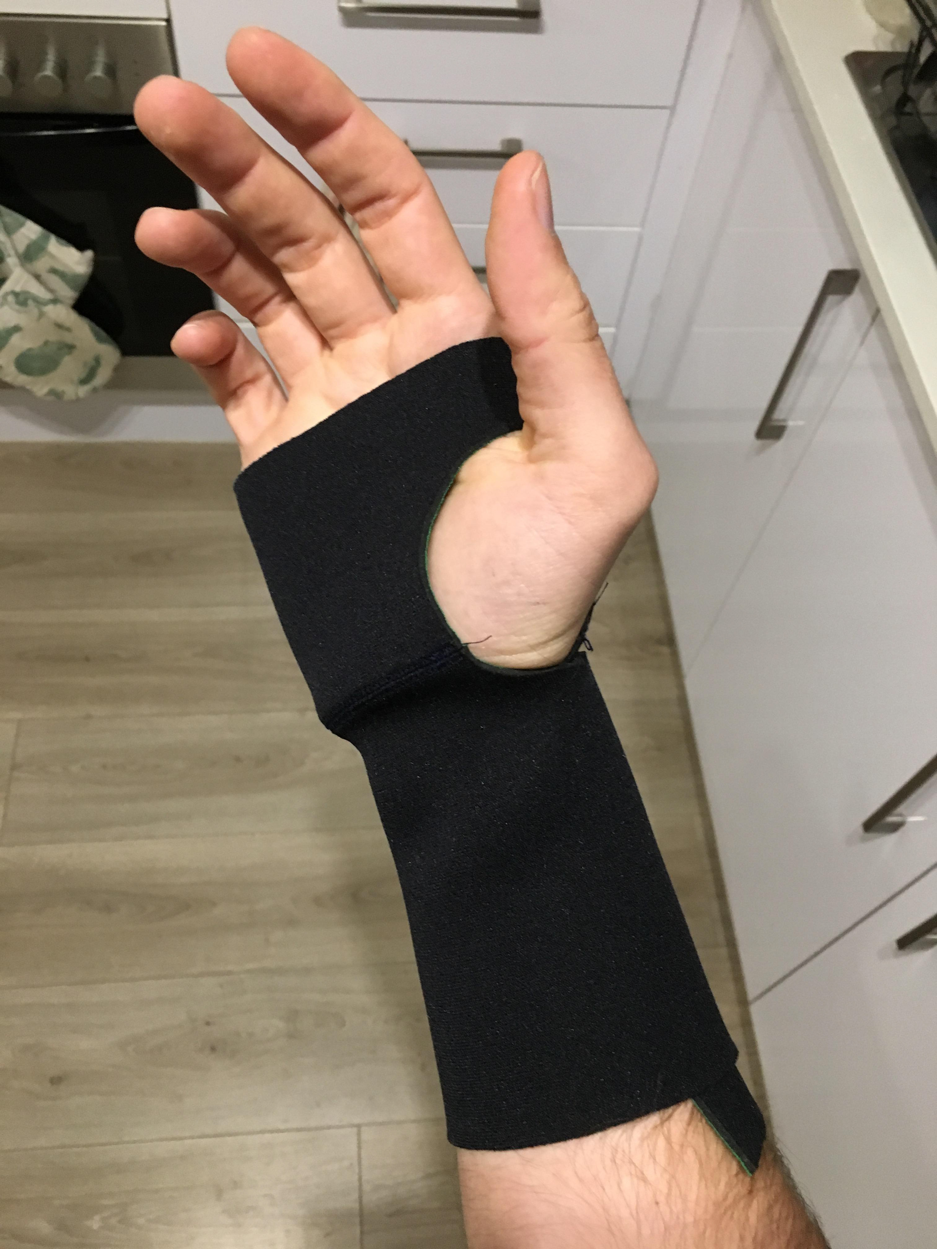
Note the lateral seam
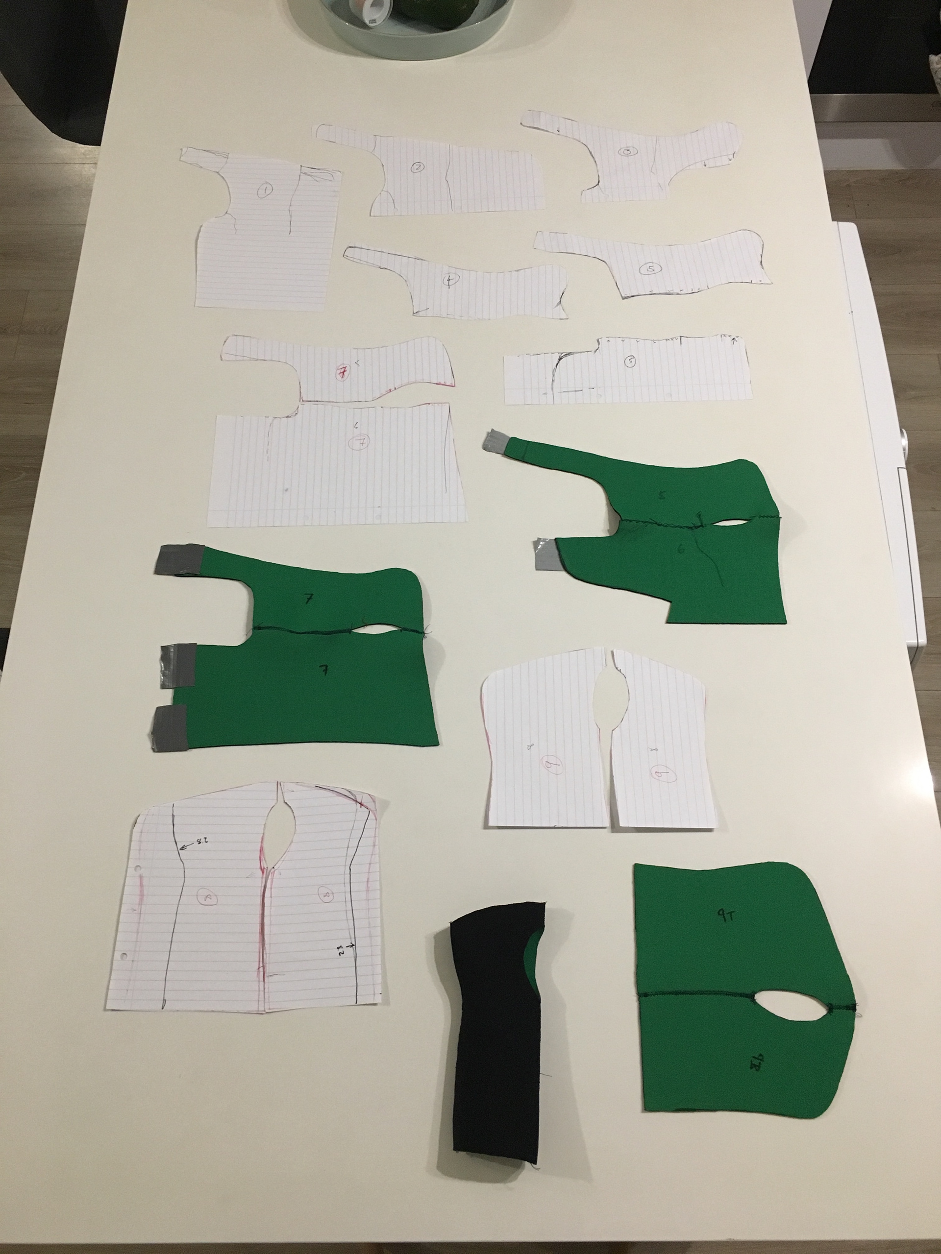
The first 8 prototypes on the kitchen counter. I'd considered using a zip on the bottom middle one...
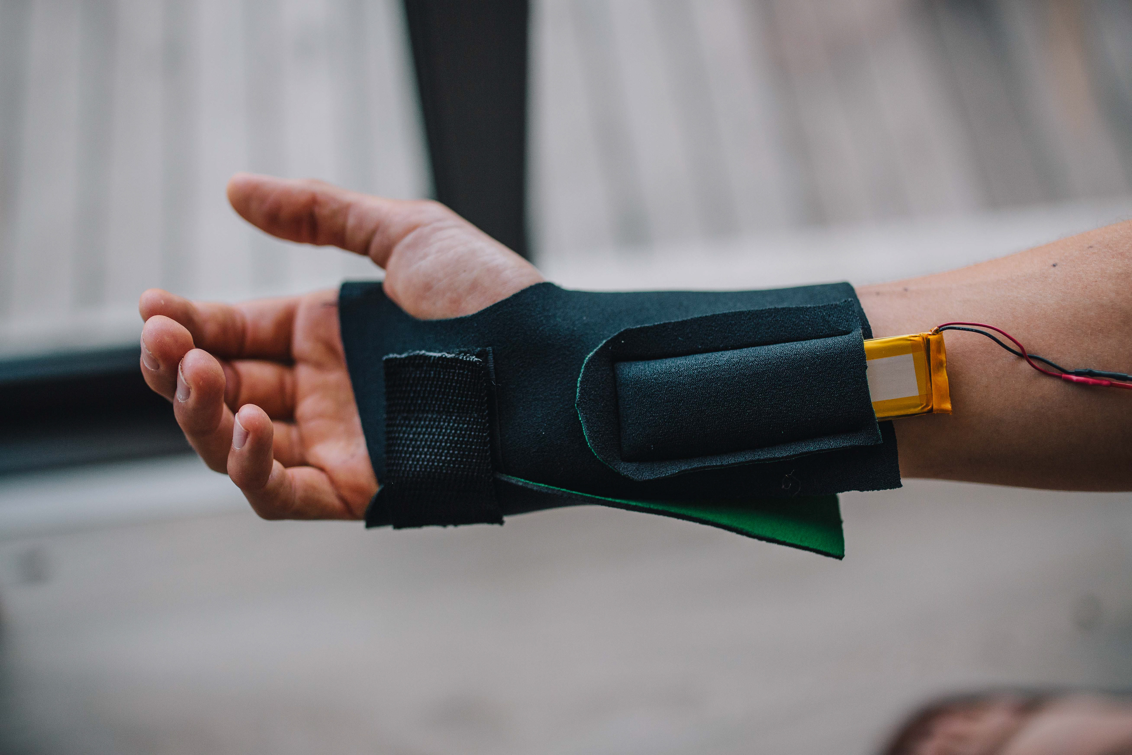
v9, testing the hand strap and a battery pouch
v10, testing different arm strap ideas
v10, testing a pouch to put the electronics into
The underside of v10, showing the battery pouches
The top of v10
v11, on a human for the first time!
The top of v11, prior to the addition of pouches
The Electrode
Dr Madden, the clinician who commissioned the design of this device, very kindly let me spend a day playing around with the kit they have in the pain studies lab. It was some pretty shocking stuff. They've never done studies involving the wrist, so this was uncharted territory for them too. Unfortunately I didn't take any pictures, but we tested everything from pin to ring electrodes, attached dry, or wet with conductive gel. We tried different shock patterns and intensities, the lot. It was great. In the end, the dry fencing lamé won the day, given its simplicity, broad contact patch and the ease with which it could be incorporated into a fabric-based design.
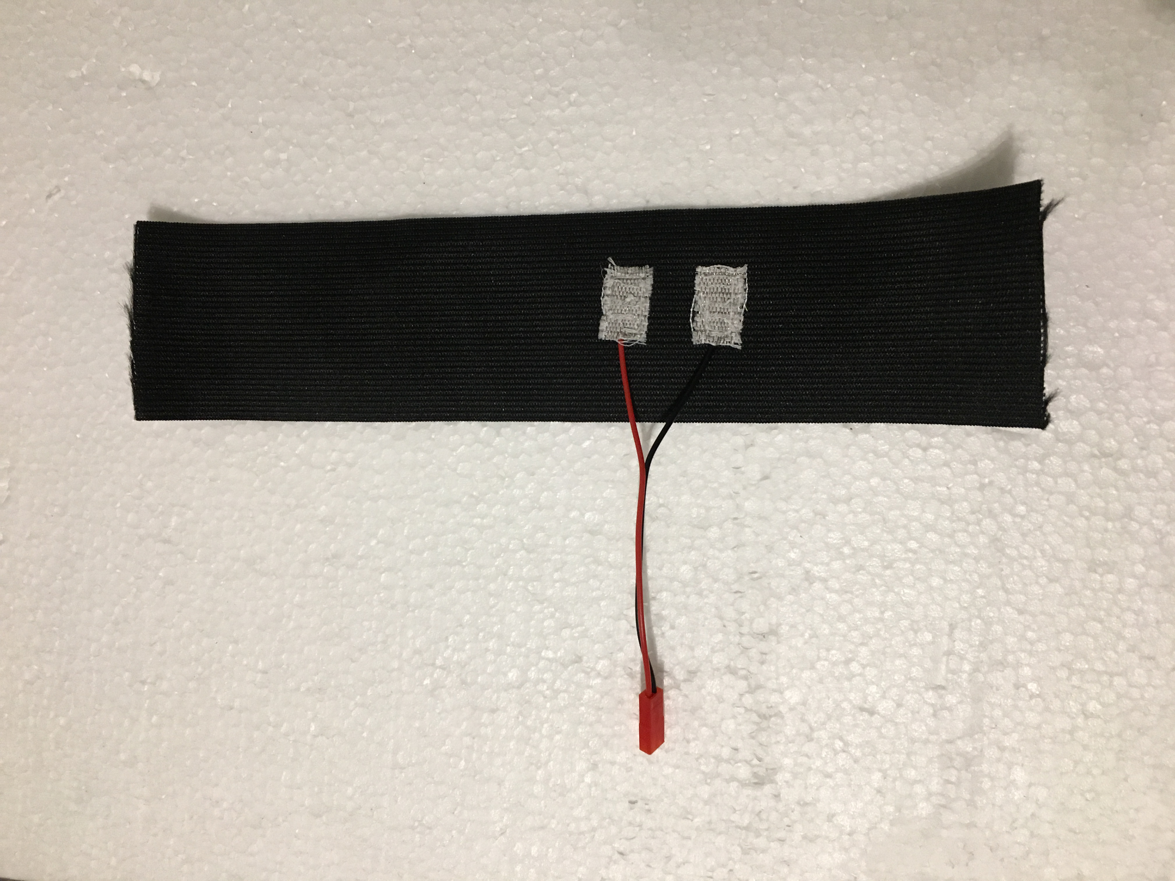
v0.5 - electrode contacts succesfully incorporated and wired up
Version 1. Was too wide and kept sliding up the arm as one moved
Version 2 (final) - a bit narrower, and with larger electrode contacts
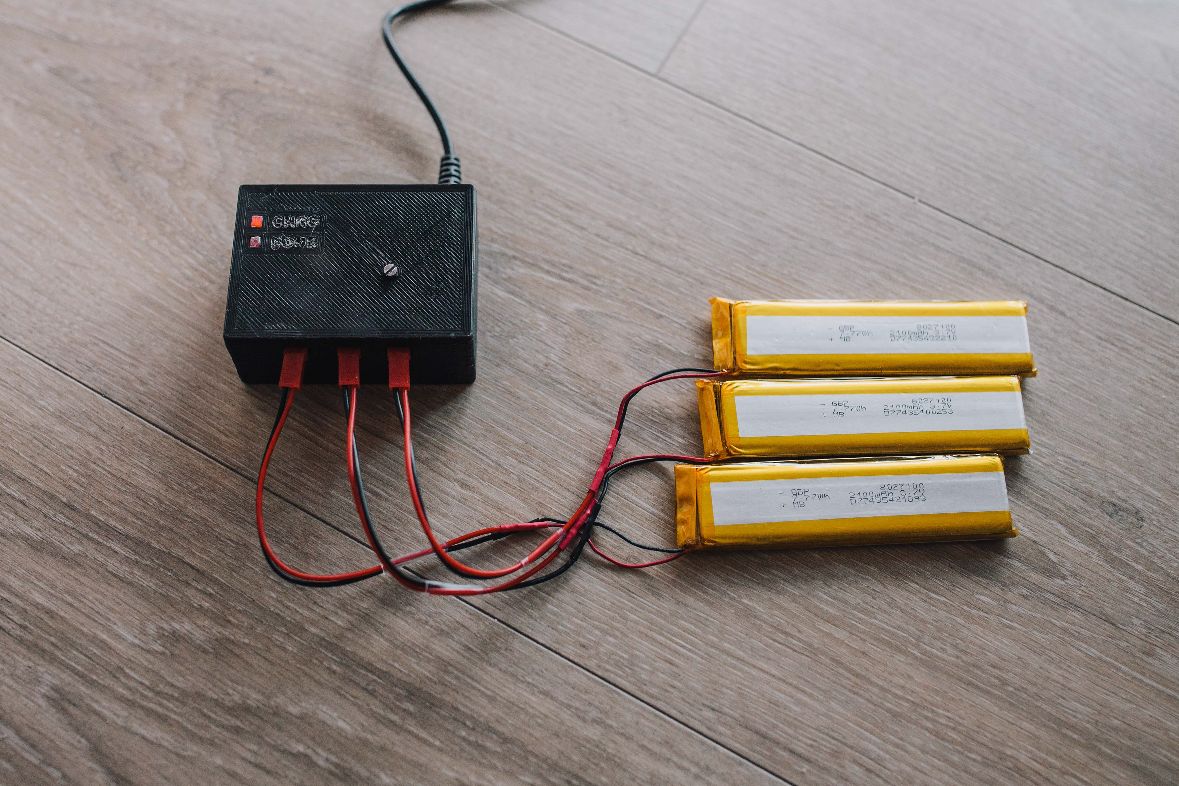
The Charger
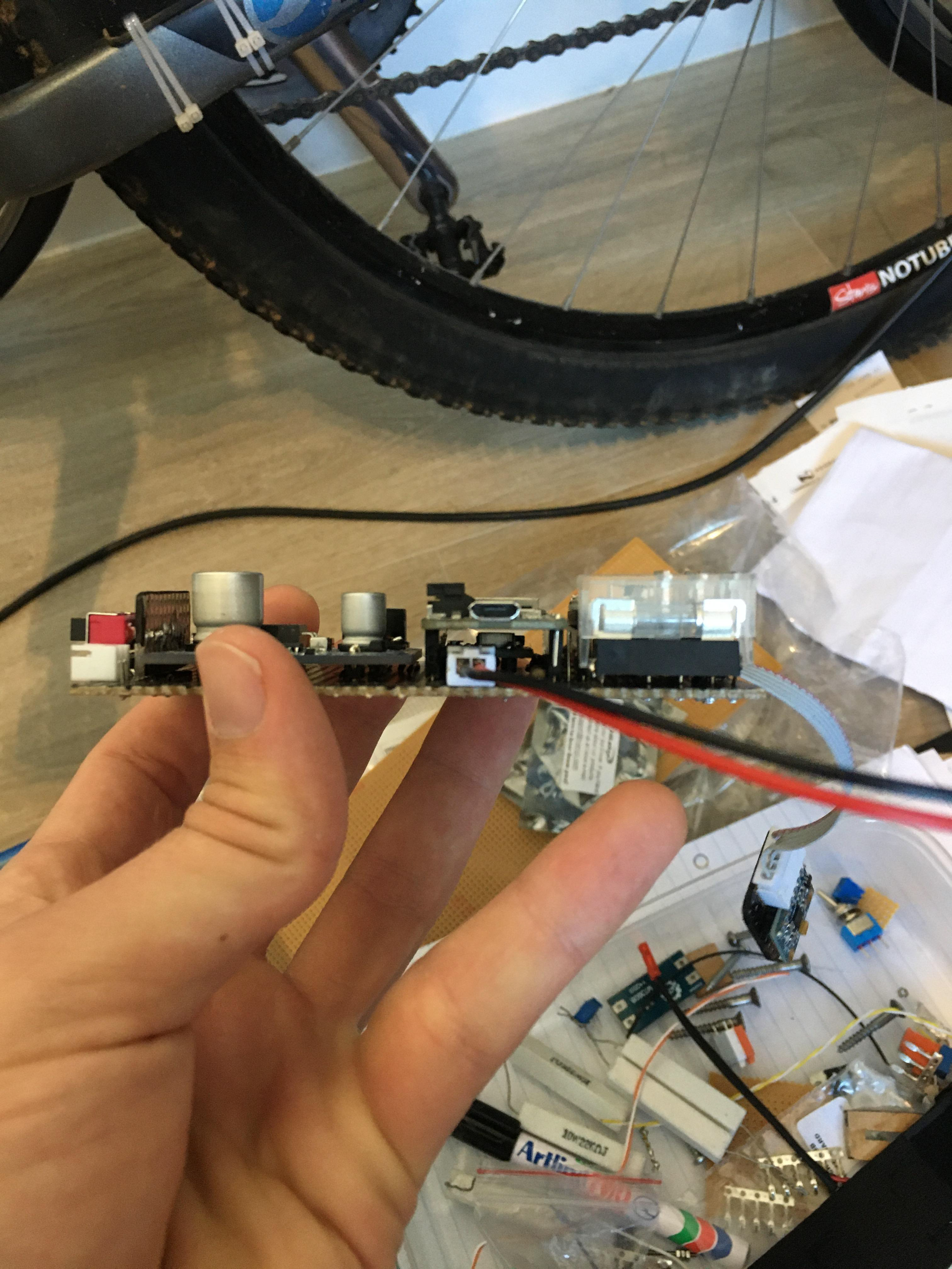
The first versions of the design incorporated an in-place charging design. The idea was that a wearer would be able to have the device charge with a standard micro-USB from a power bank while they worked or slept... To this end, the first circuit board included a micro-USB breakout and a 5V to 12.6V boost convertor. In hindsight this was wild wishful thinking, but was worth a shot. The setup drew about an amp, and was taking up a lot of precious space on the circuit board. An executive decision was taken to scrap in-place charging in favour of an outboard charger - a wearer has two sets of batteries and swaps them out when dead.
The charger is powered by a standard 12V, 2A power supply module. The 12V input is boosted to 18V to supply a charger chip which implements a two-phased constant current and constant voltage charging routine, charging the three batteries in series to 12.6V.
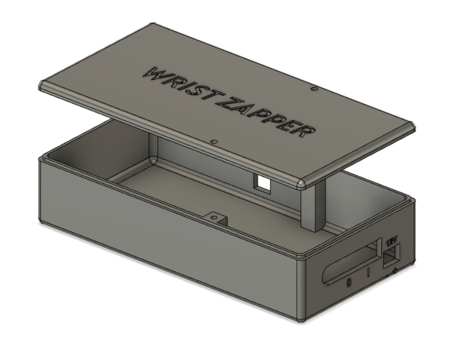
Once the board was made I designed a case in Autodesk Fusion 360, which I had 3D-printed. It took a little wiggling to get the board in, but in the end it fitted like a glove. I was incredibly stoked that the 12V plug hole was correctly dimensioned - there wasn't much room for manoeuvre!
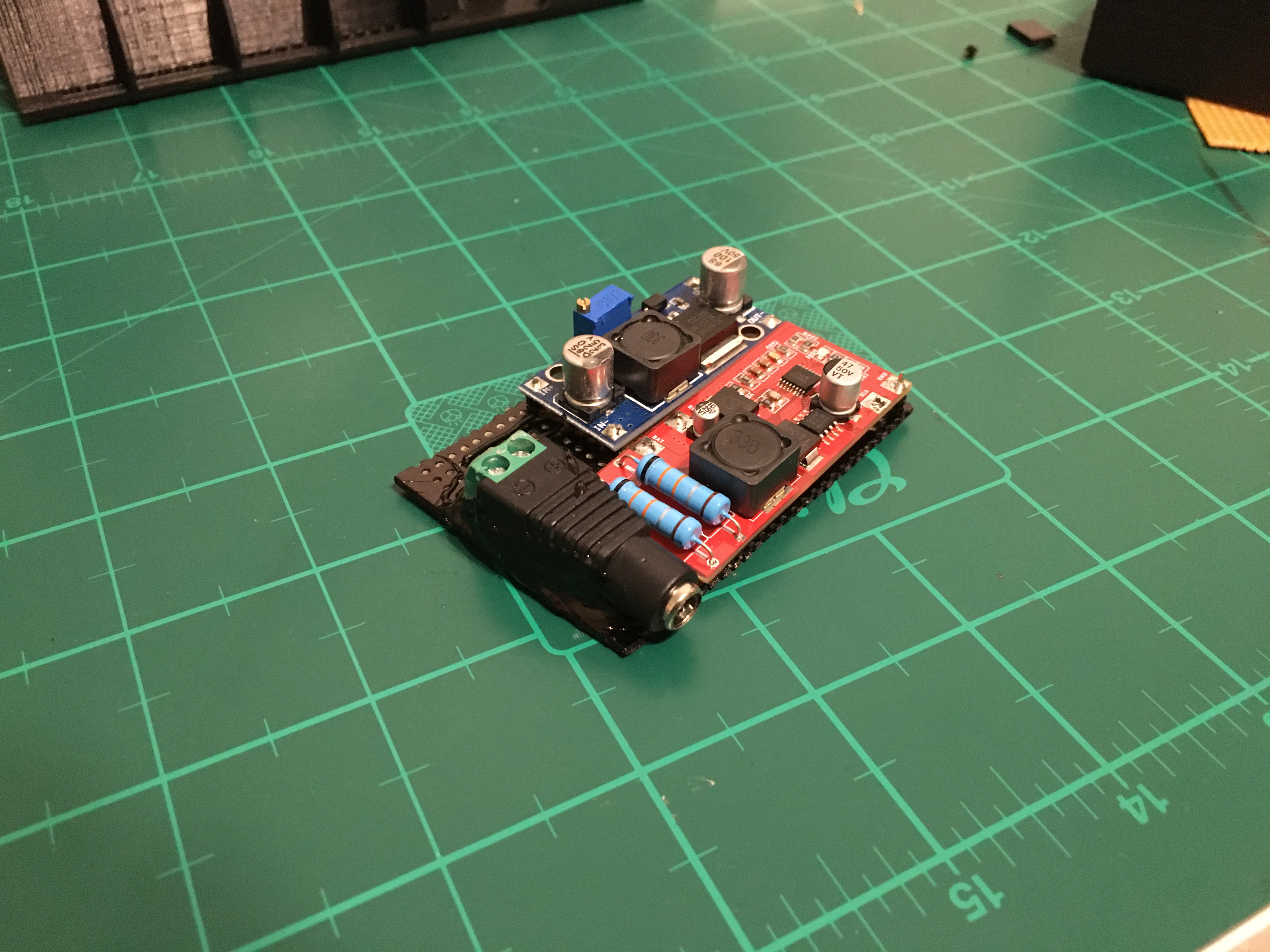
The board, all done
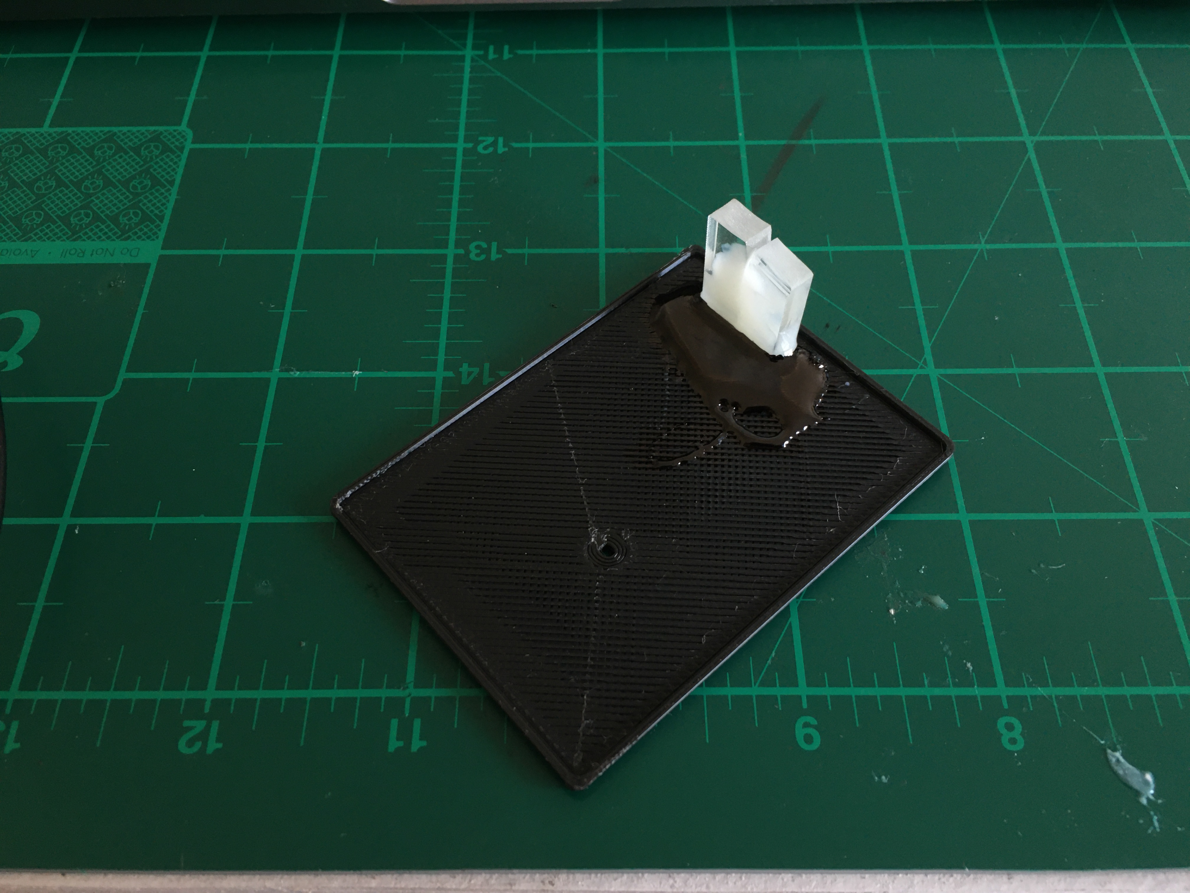
Two pieces of Perspex glued into the lid to transmit the "Charging" and "Done" LEDs to the outside world.
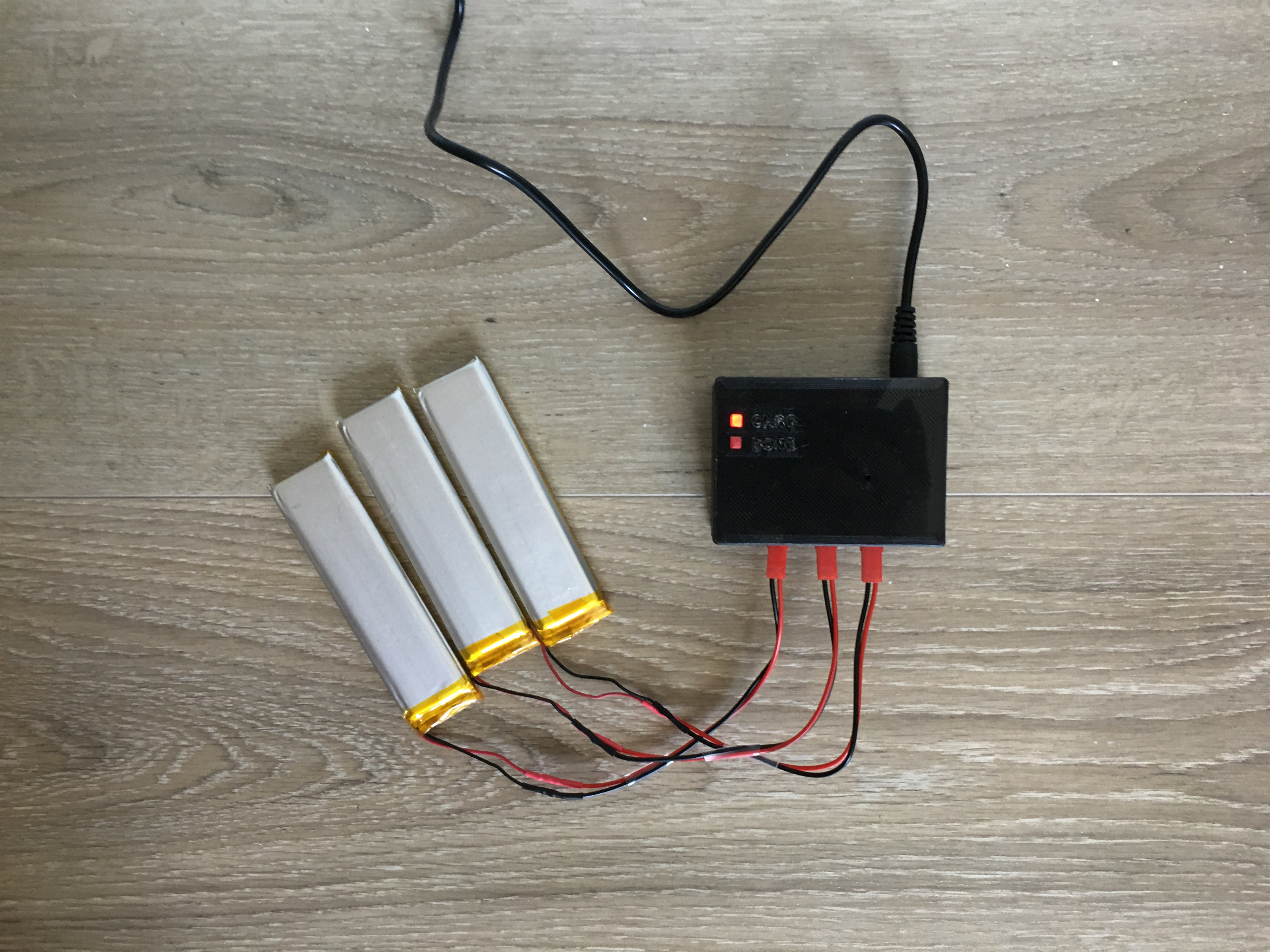
The final thing in action
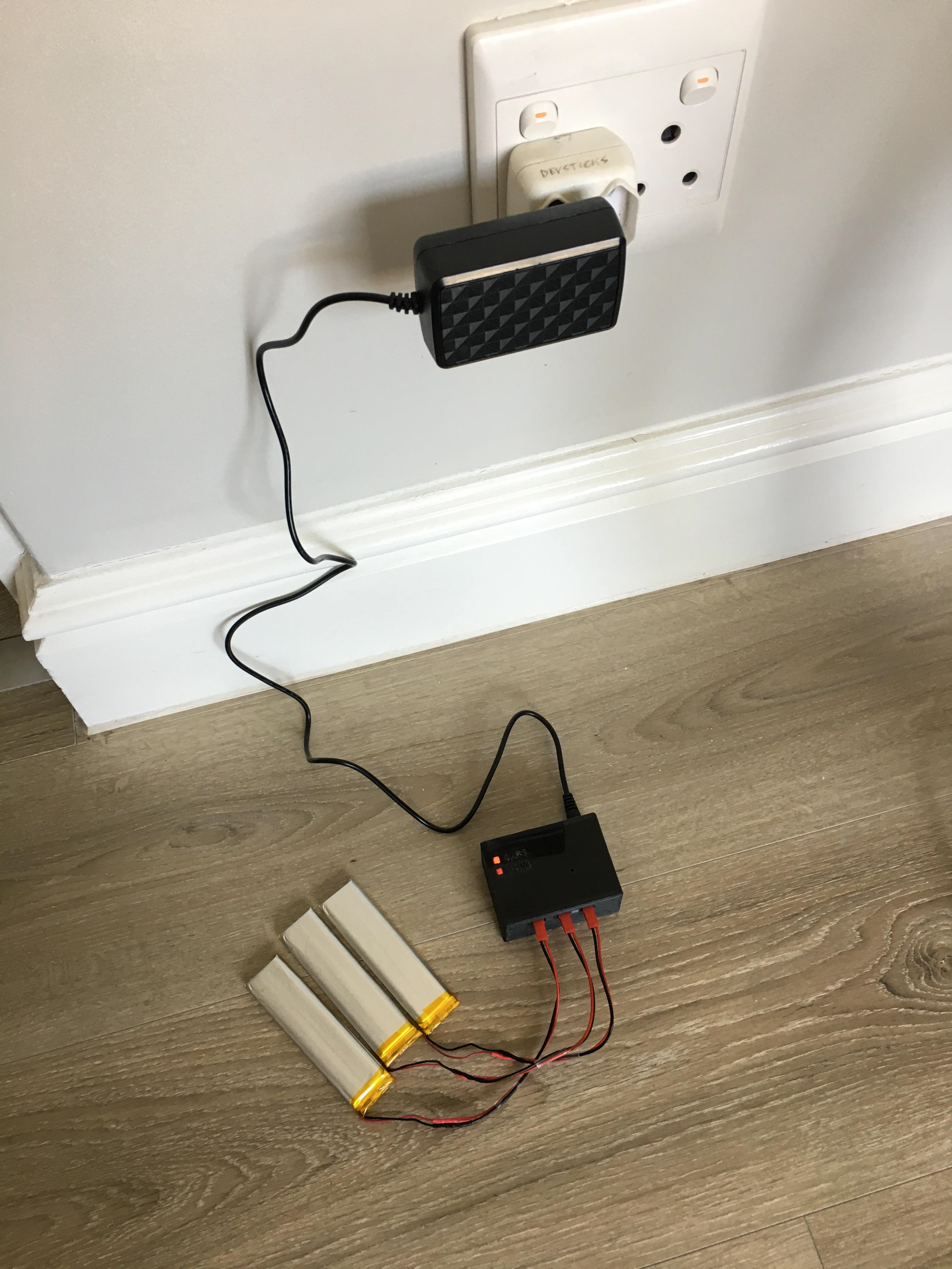
The whole setup, including the 12V wall module
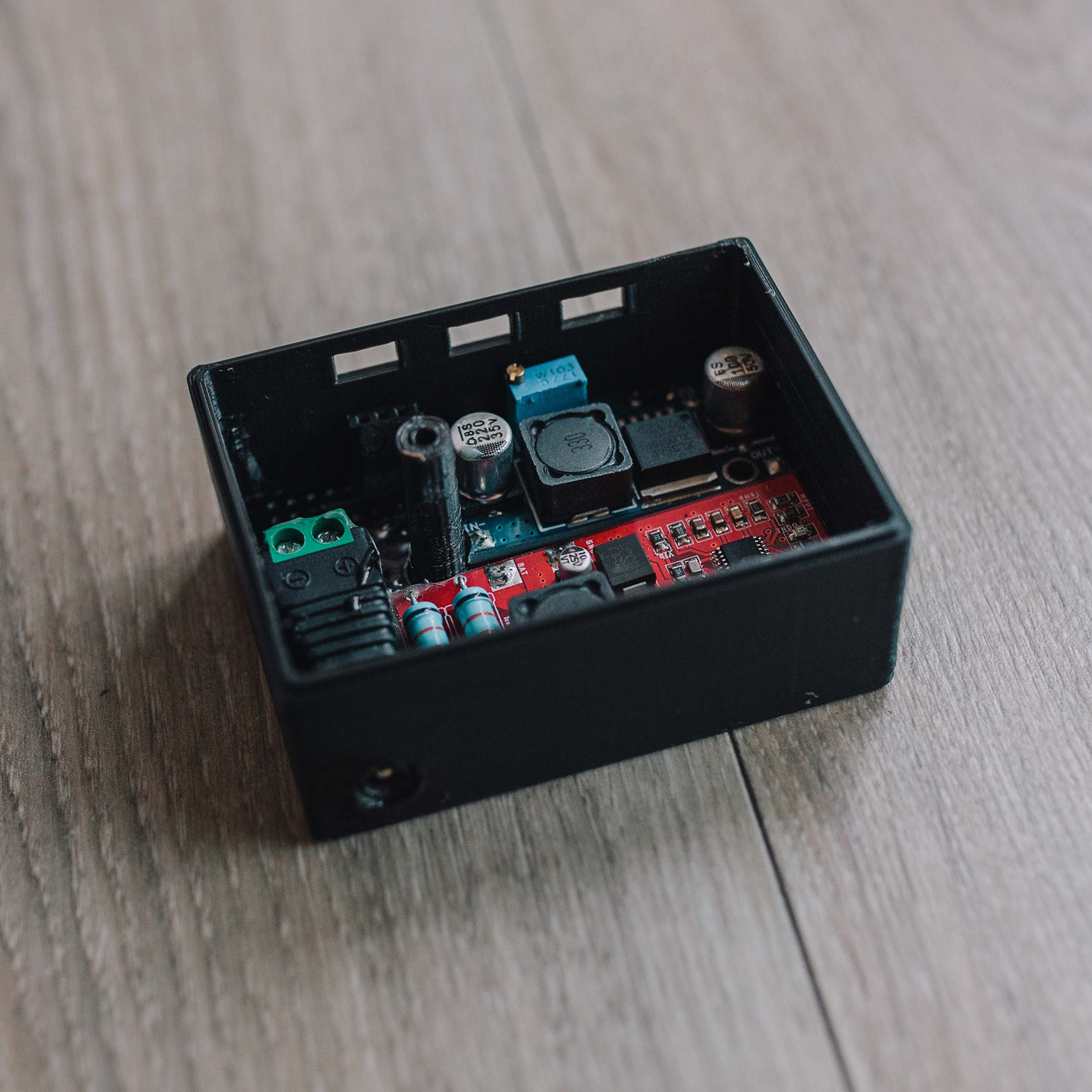
A closeup of the base circuit board in its case (the battery sockets were added afterwards)
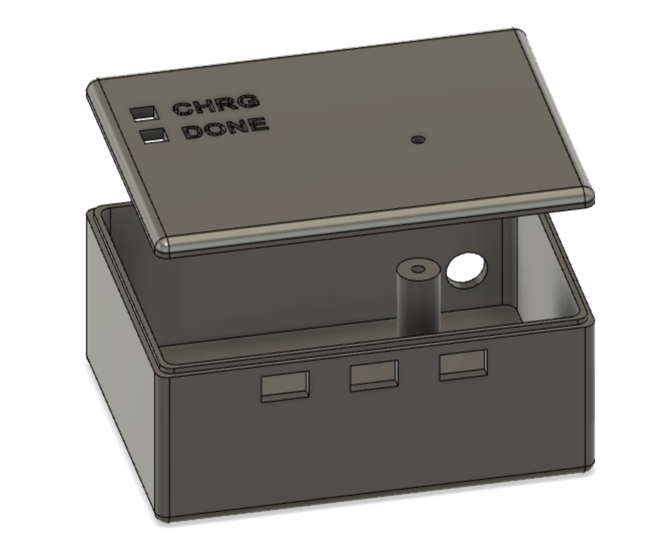
The 3D printed enclosure design
Testing
Test Hardware
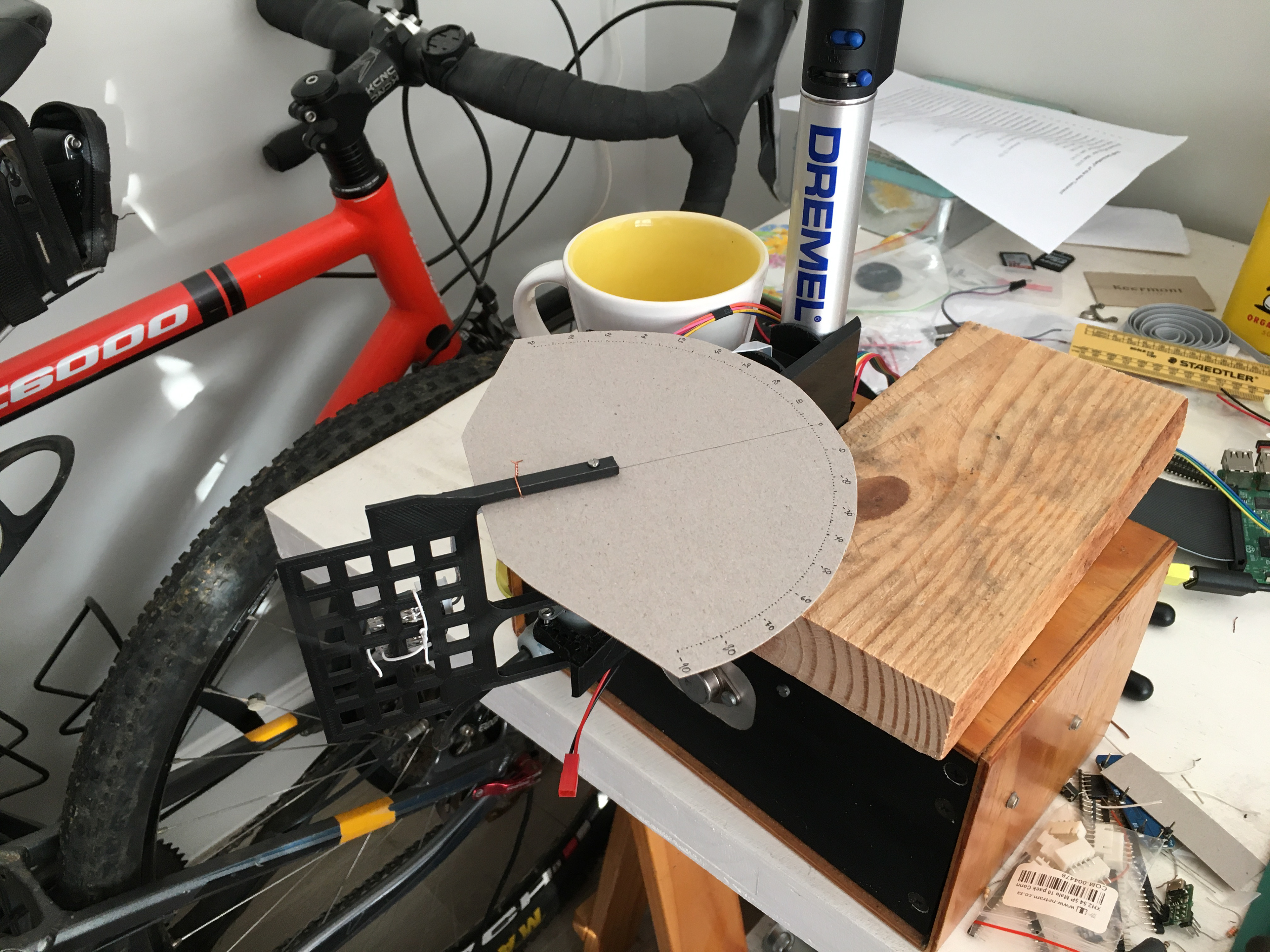
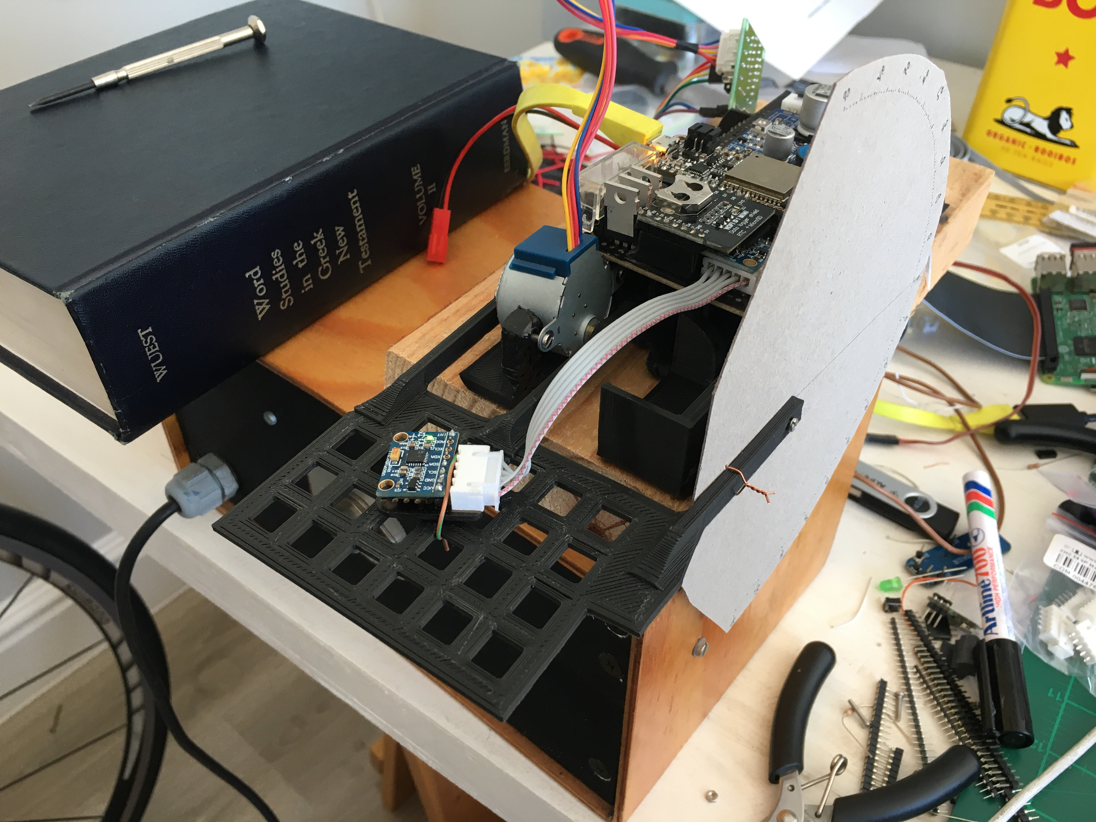
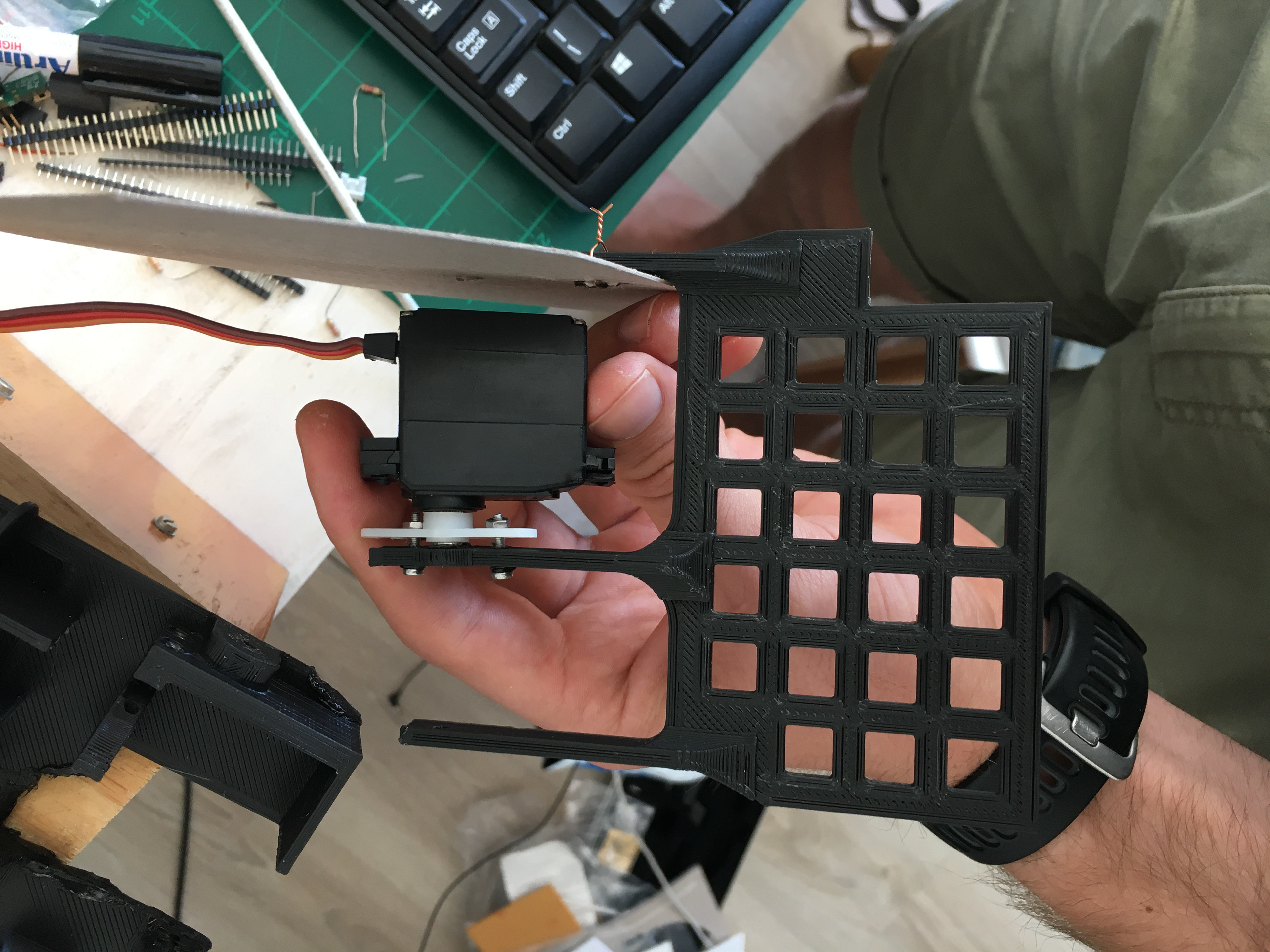
In order to test various aspects of the device performance such as it's accuracy in wrist angle estimation while still or moving and its durability under repeated movement, a physical wrist analog was designed. This first analog, made from pine wood and articulated by a door hinge, fitted the sleeve very well, but proved too heavy for the stepper motor to lift. Following this failure, a lightweight form was 3D-printed, with space to house both a stepper motor and a servo motor. The form worked excellently for its purpose. The specifics of each test performed with this apparatus can be found in the image captions and the videos below.
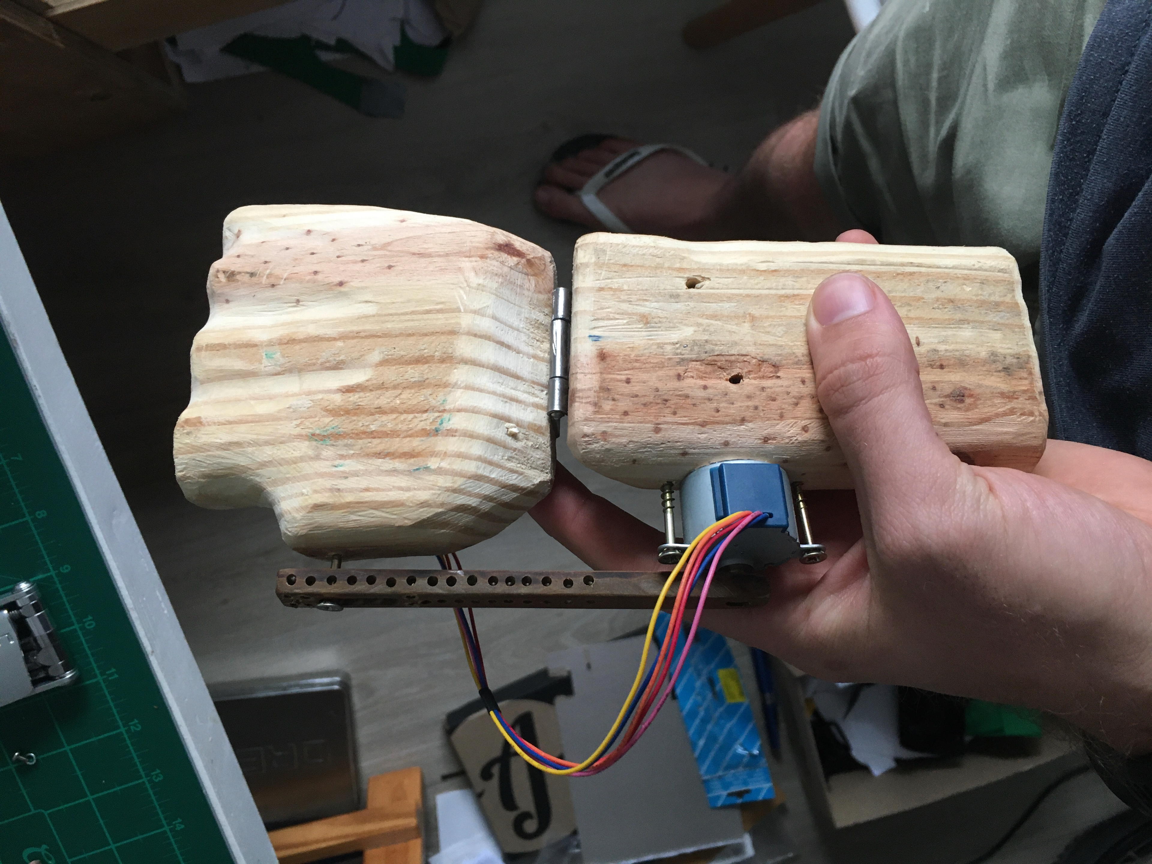
The first angle testing rig, fashioned from some pine with a door hinge in the middle. Proved far too heavy for the stepper motor to manipulate
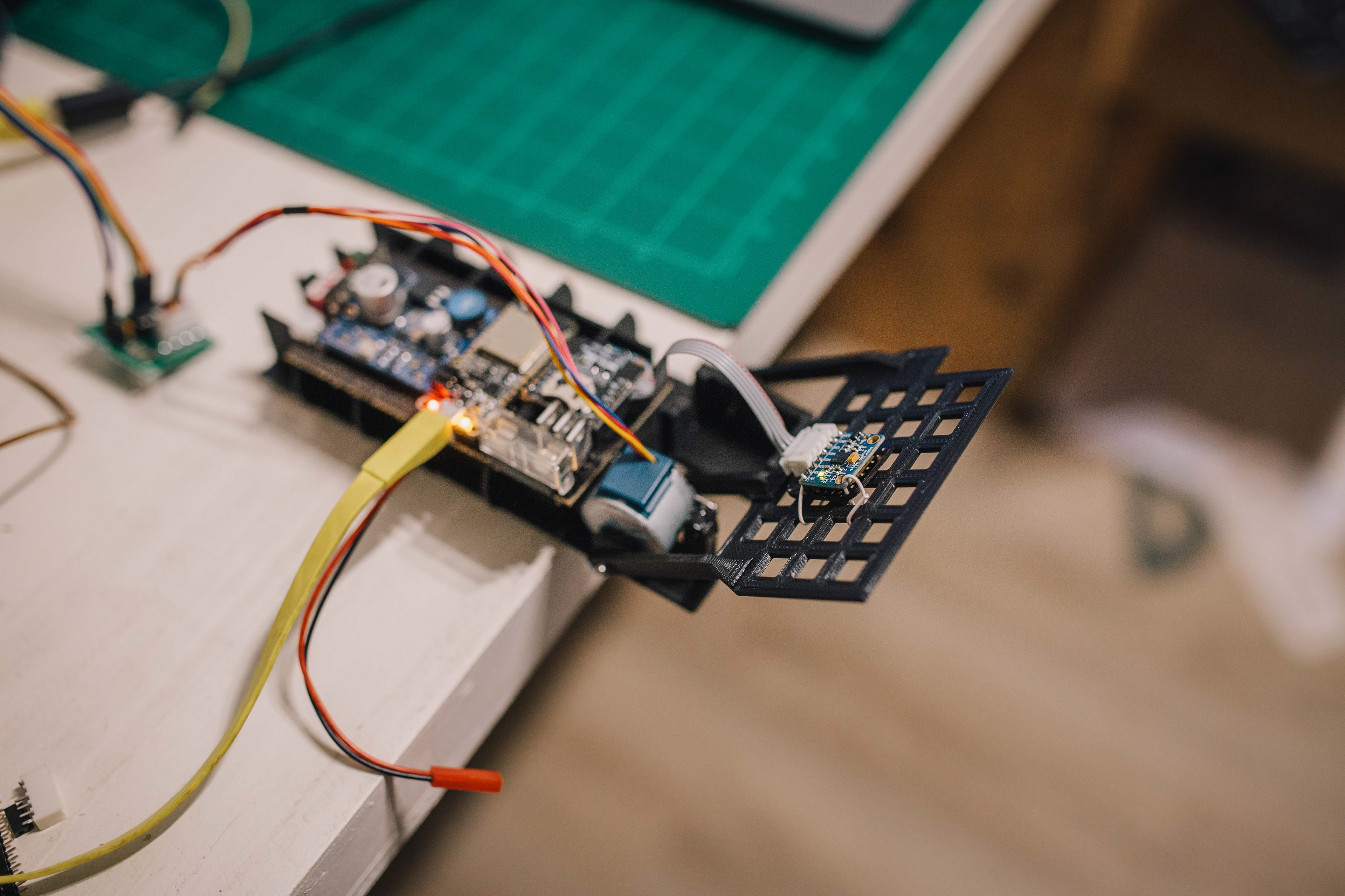
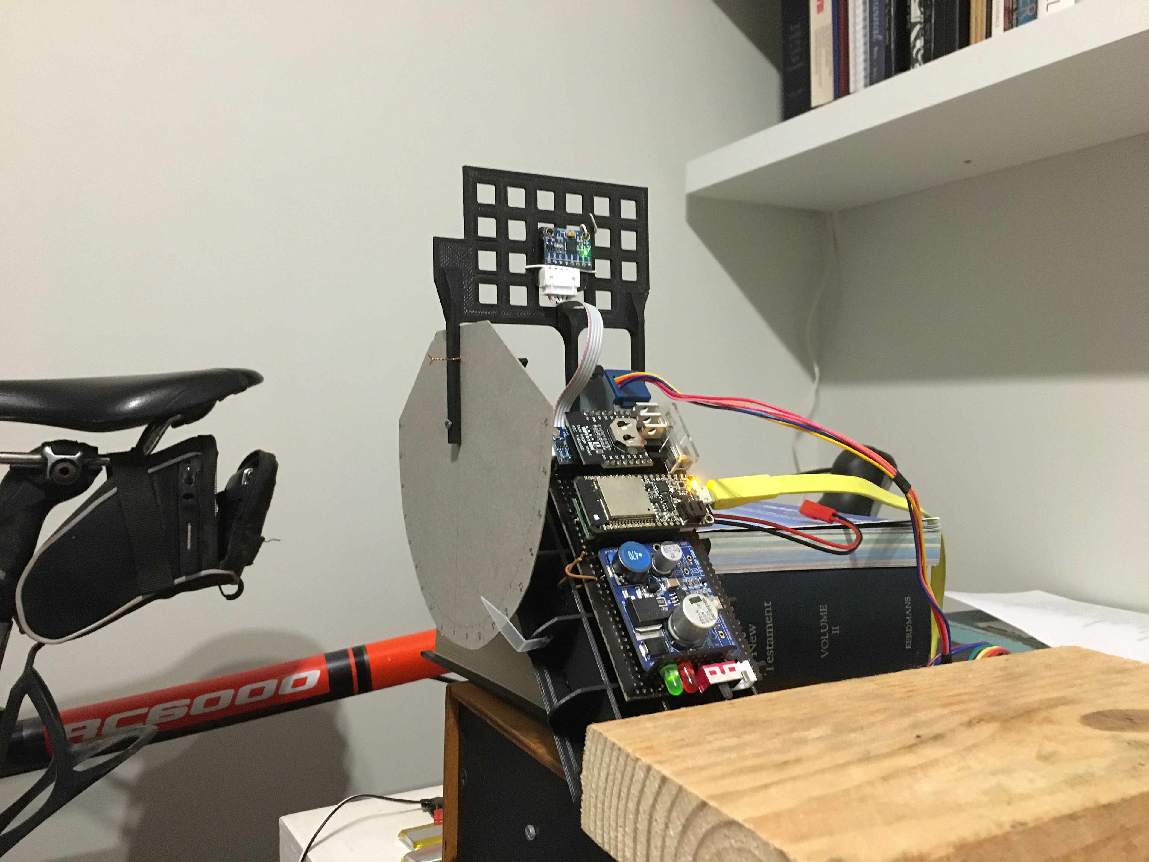
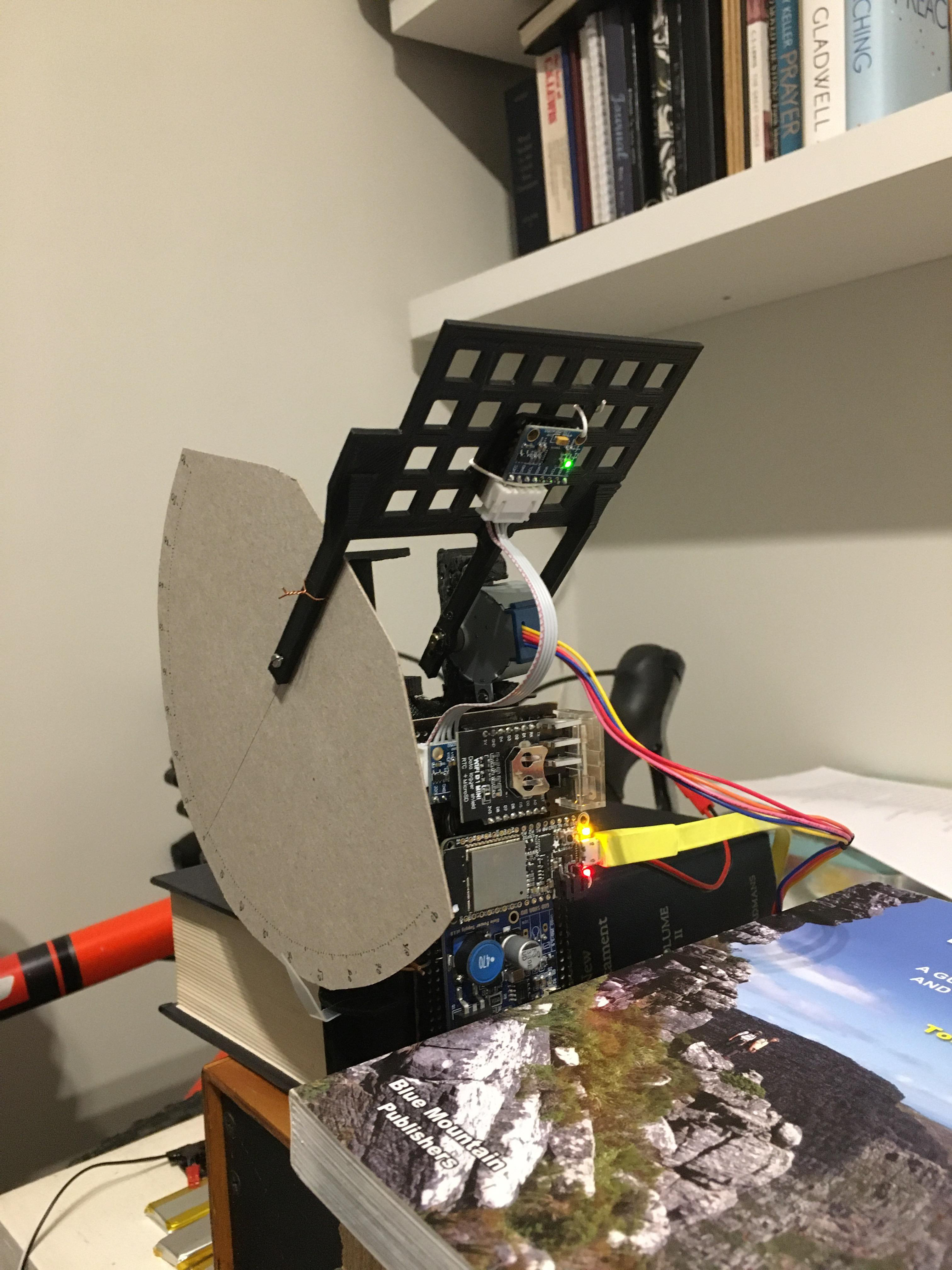
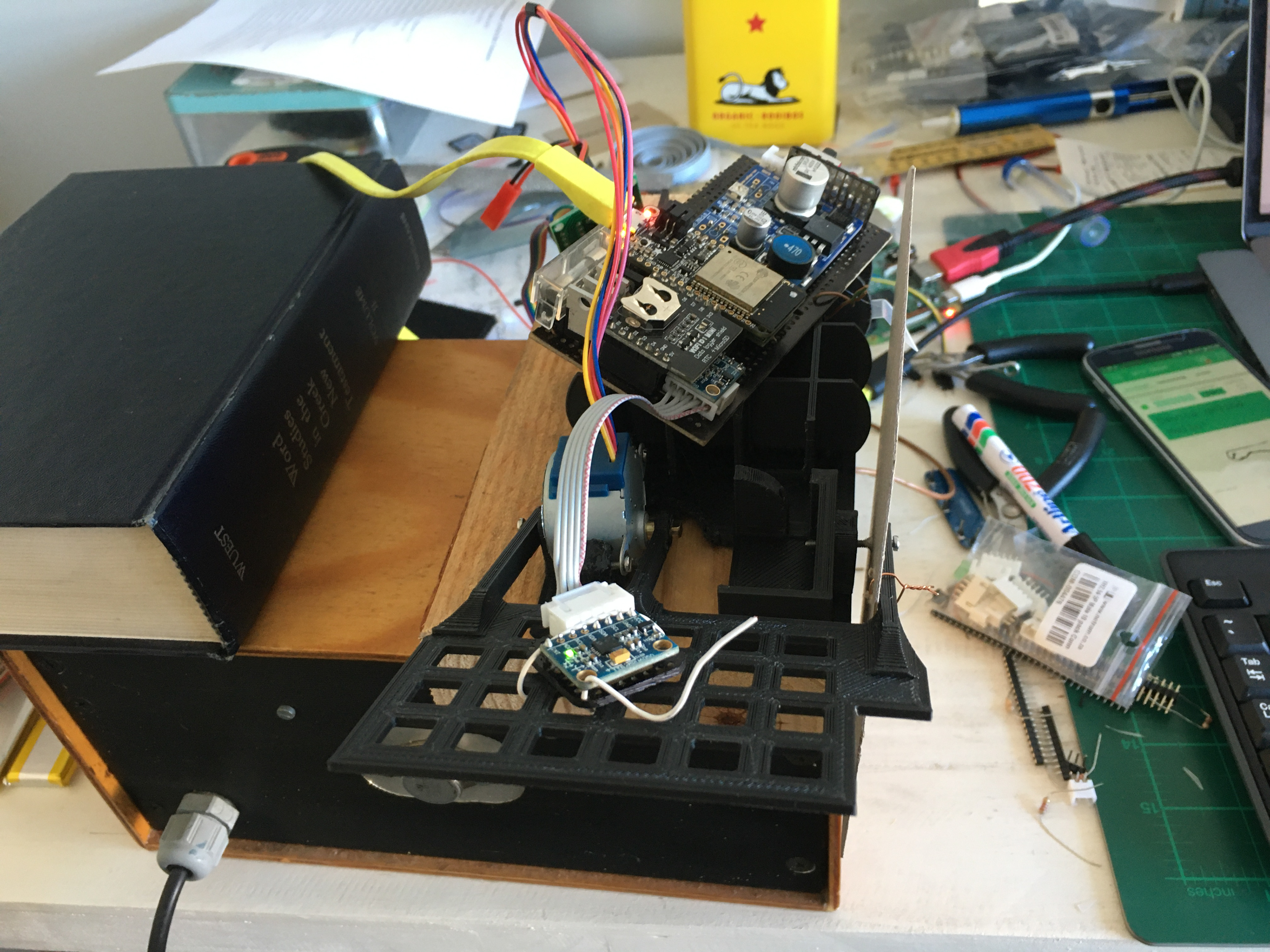
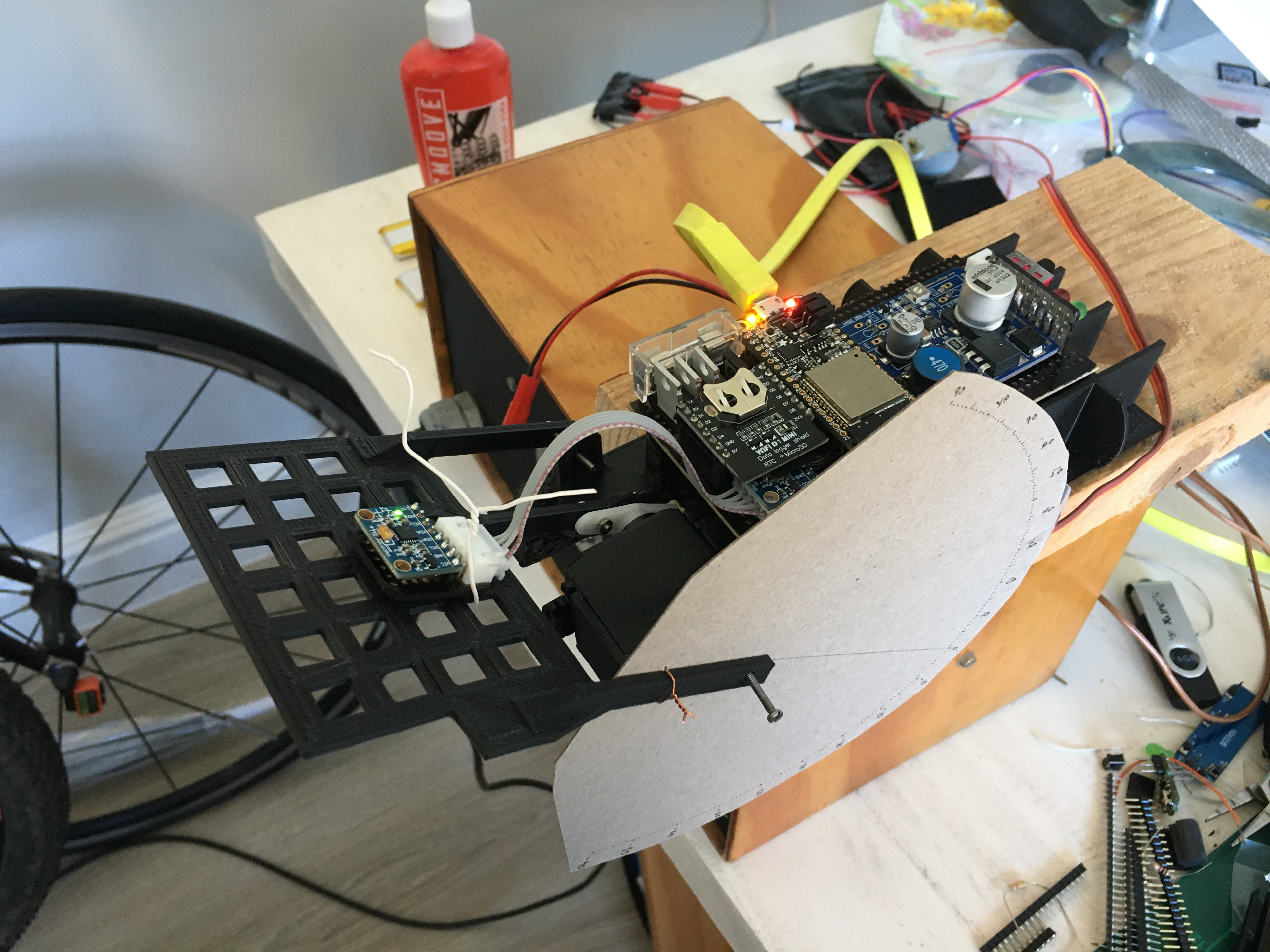
The 3D-printed angle testing apparatus, set up and ready to go
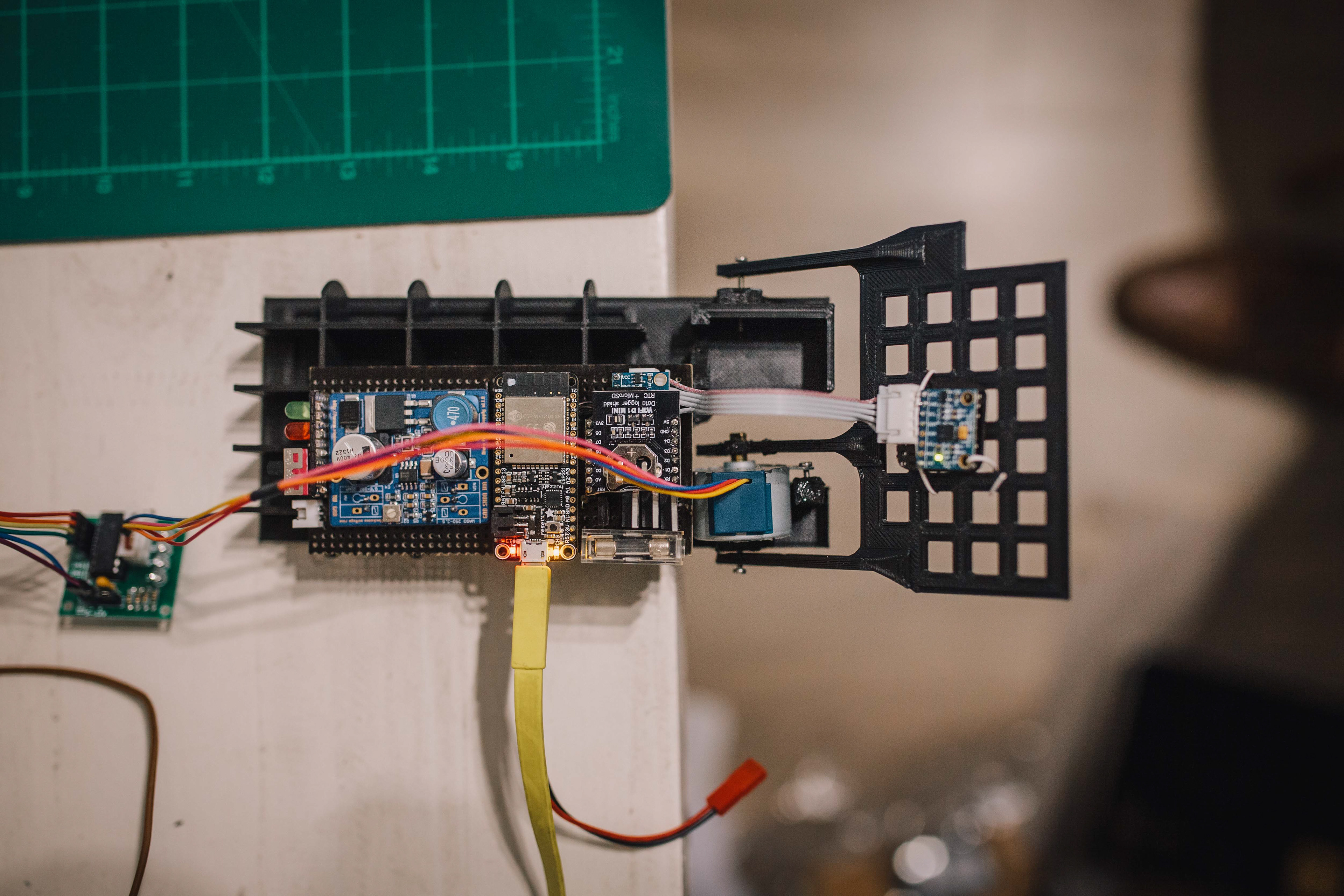
The stepper motor ready for static tests
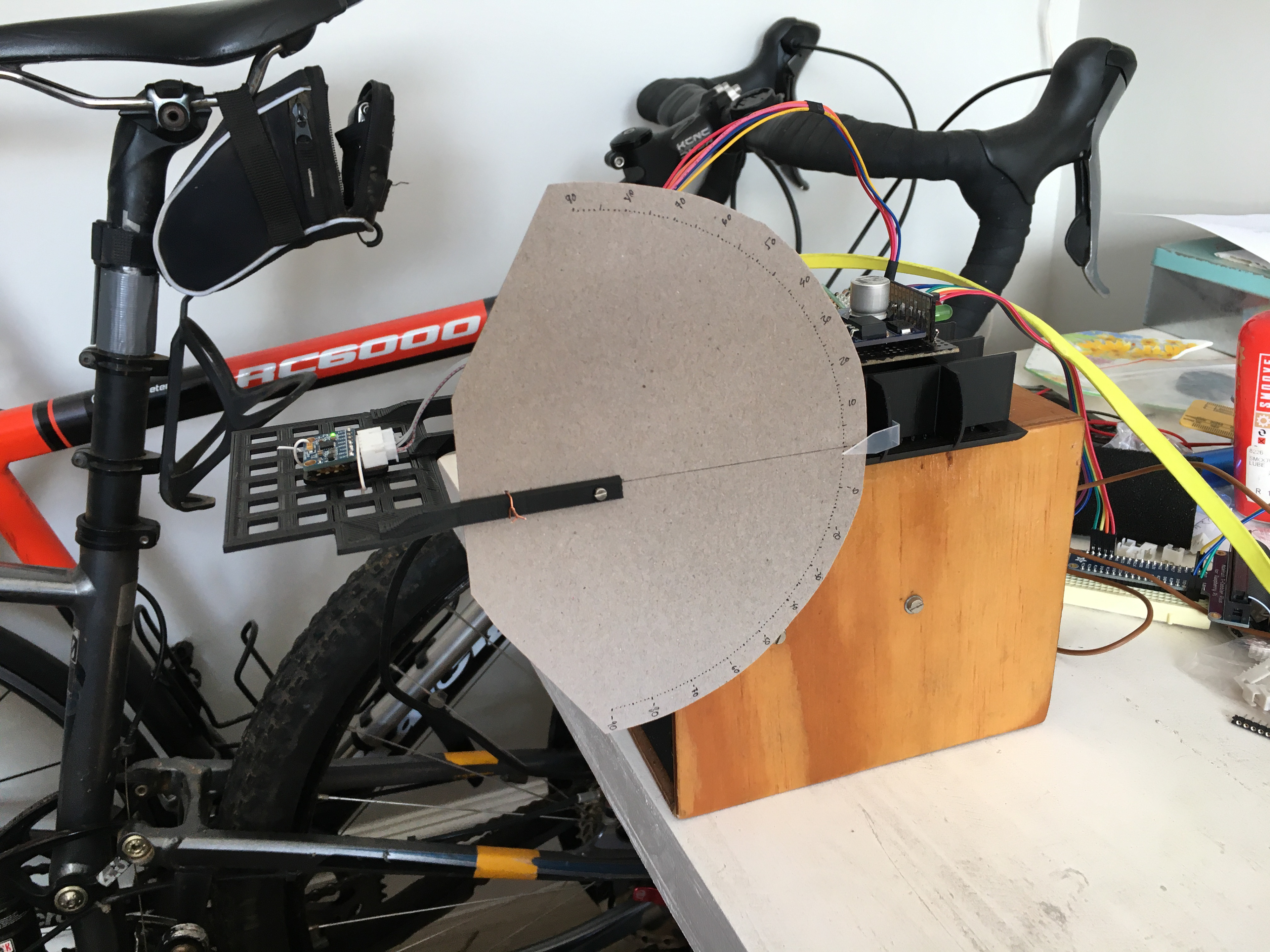
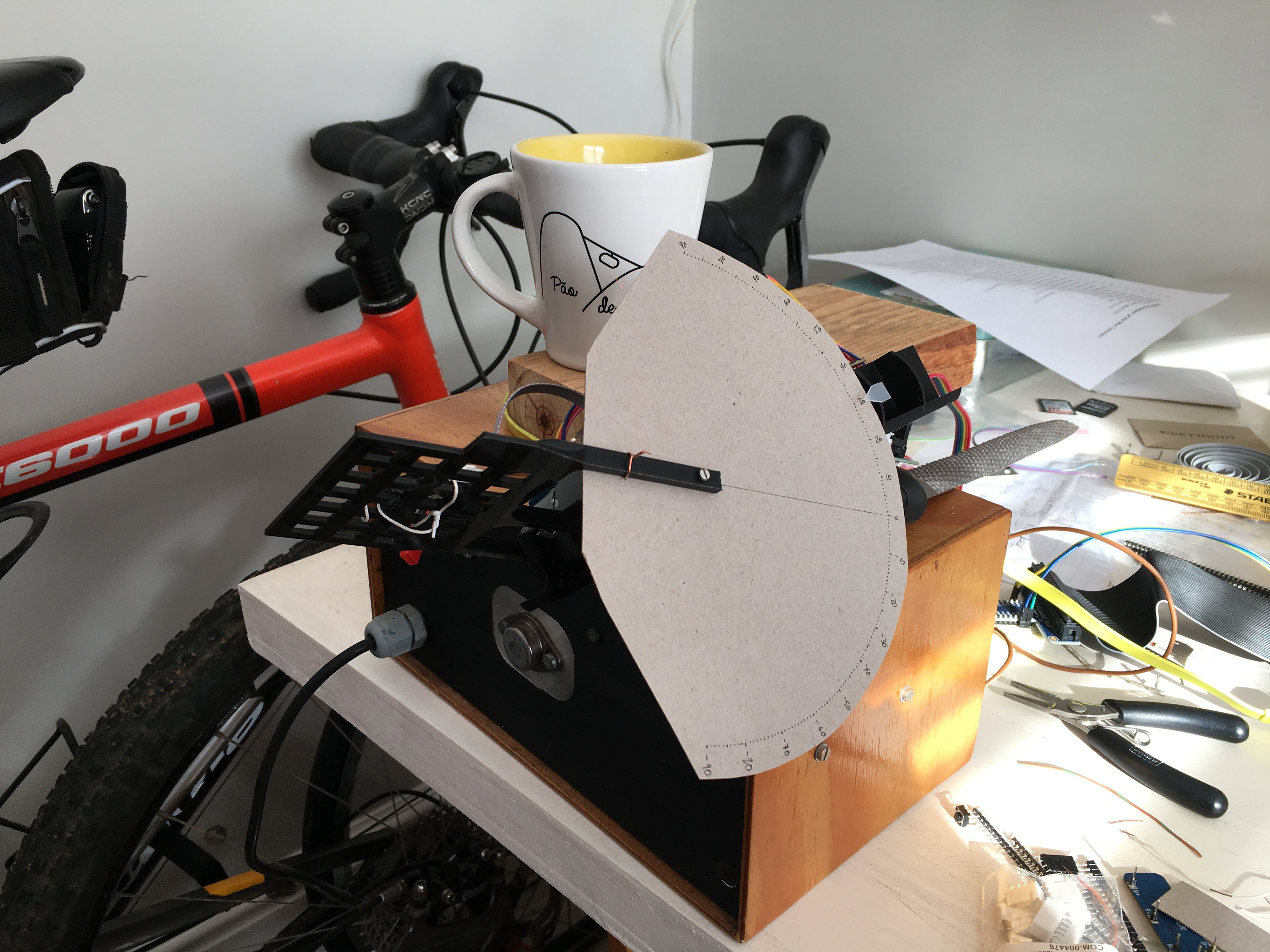
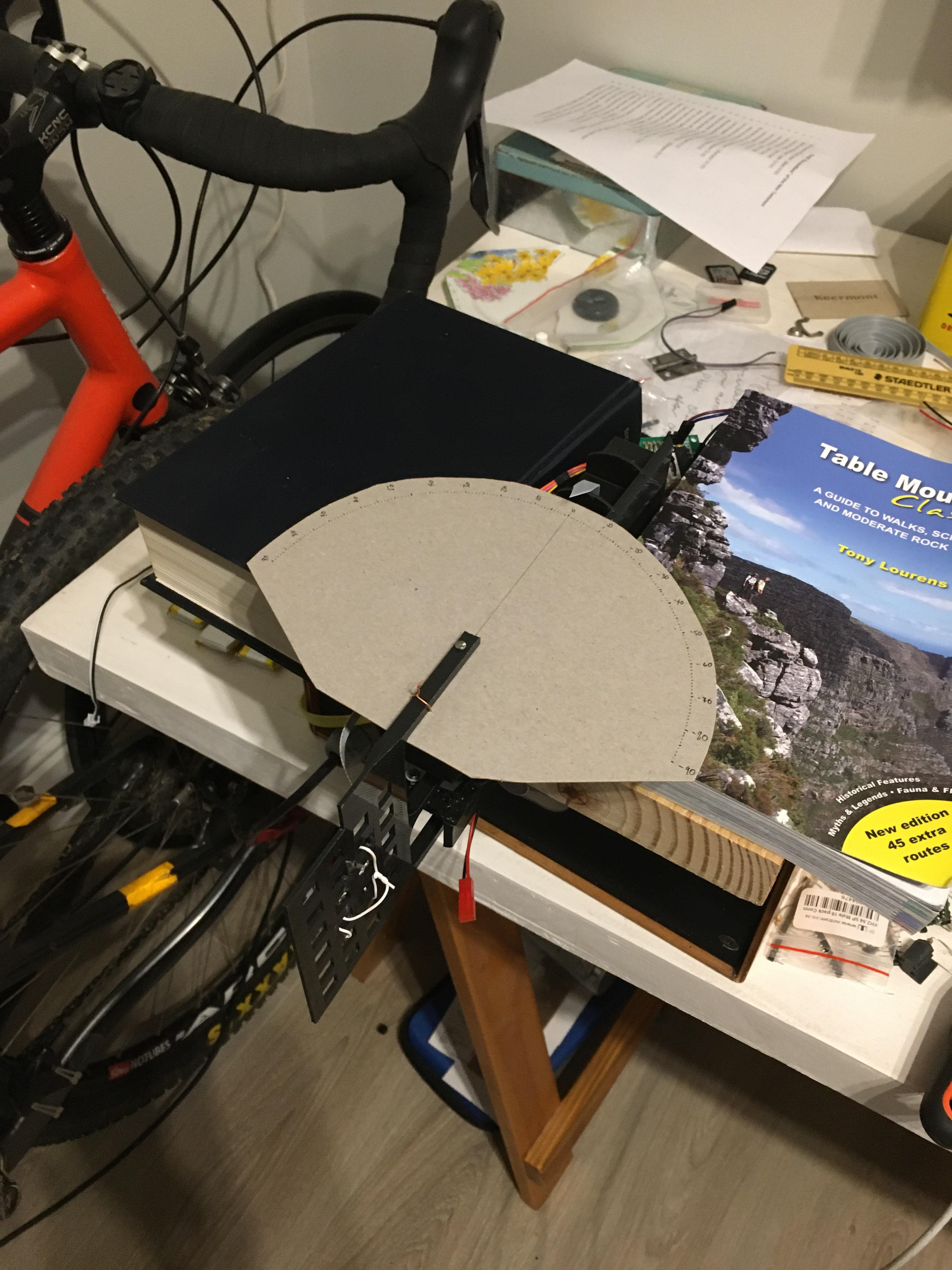
It proved difficult to measure the angle to verify the stepper motor's angle, so I added a protractor. Marker made from a Milo tin lid!
Static testing at 45 degrees roll
Static testing at 90 degrees roll. Securing the lot became good fun....
Nothing like Tony Lourens and Word Studies in the Greek New Testament to hold down the fort!
Static testing at 45 degrees pitch
Static testing at 90 degrees pitch
Static testing with a poor sensor-to-segment alignment
Static testing with a very poor sensor-to-segment alignment
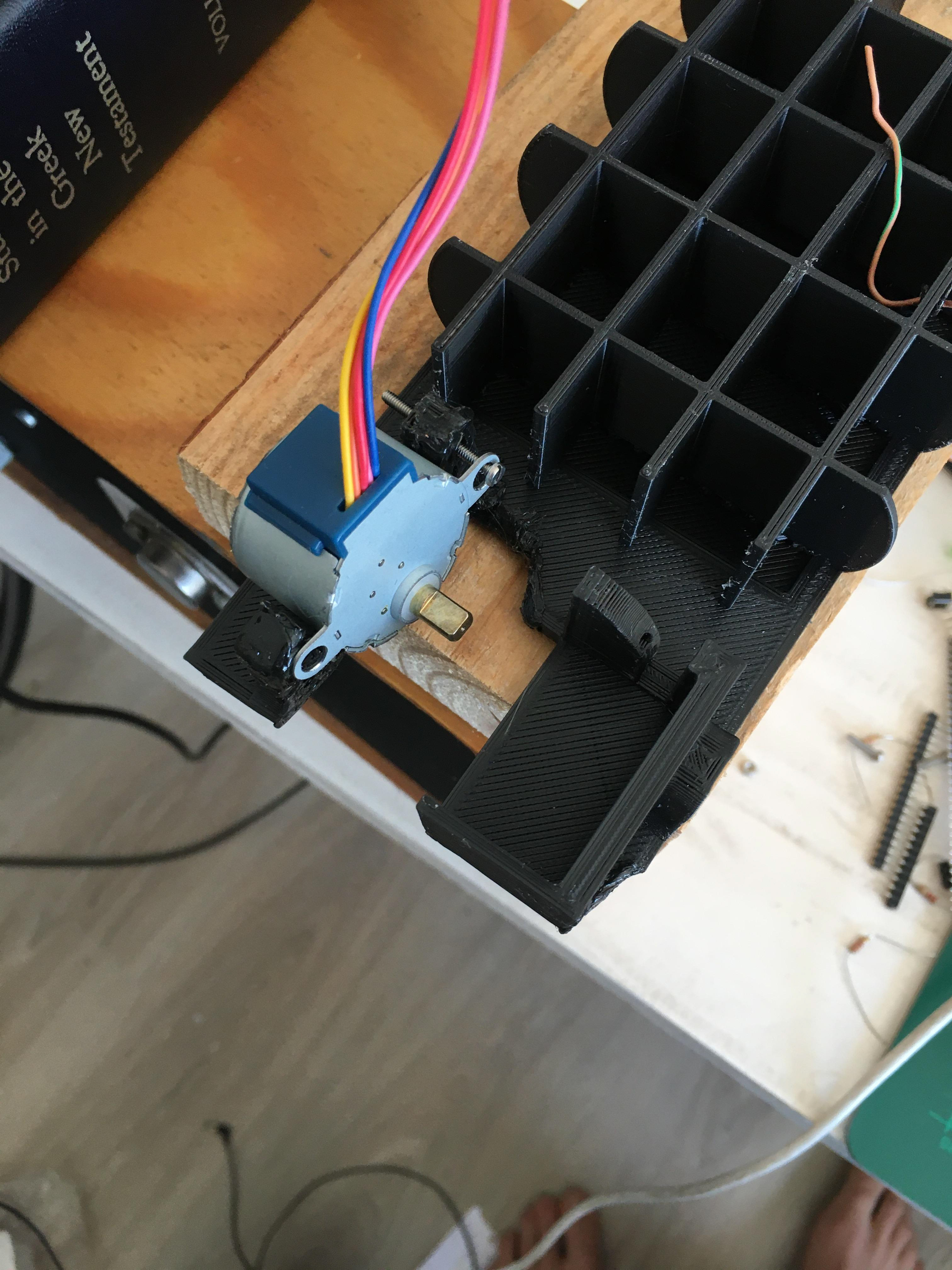
Just the stepper in place
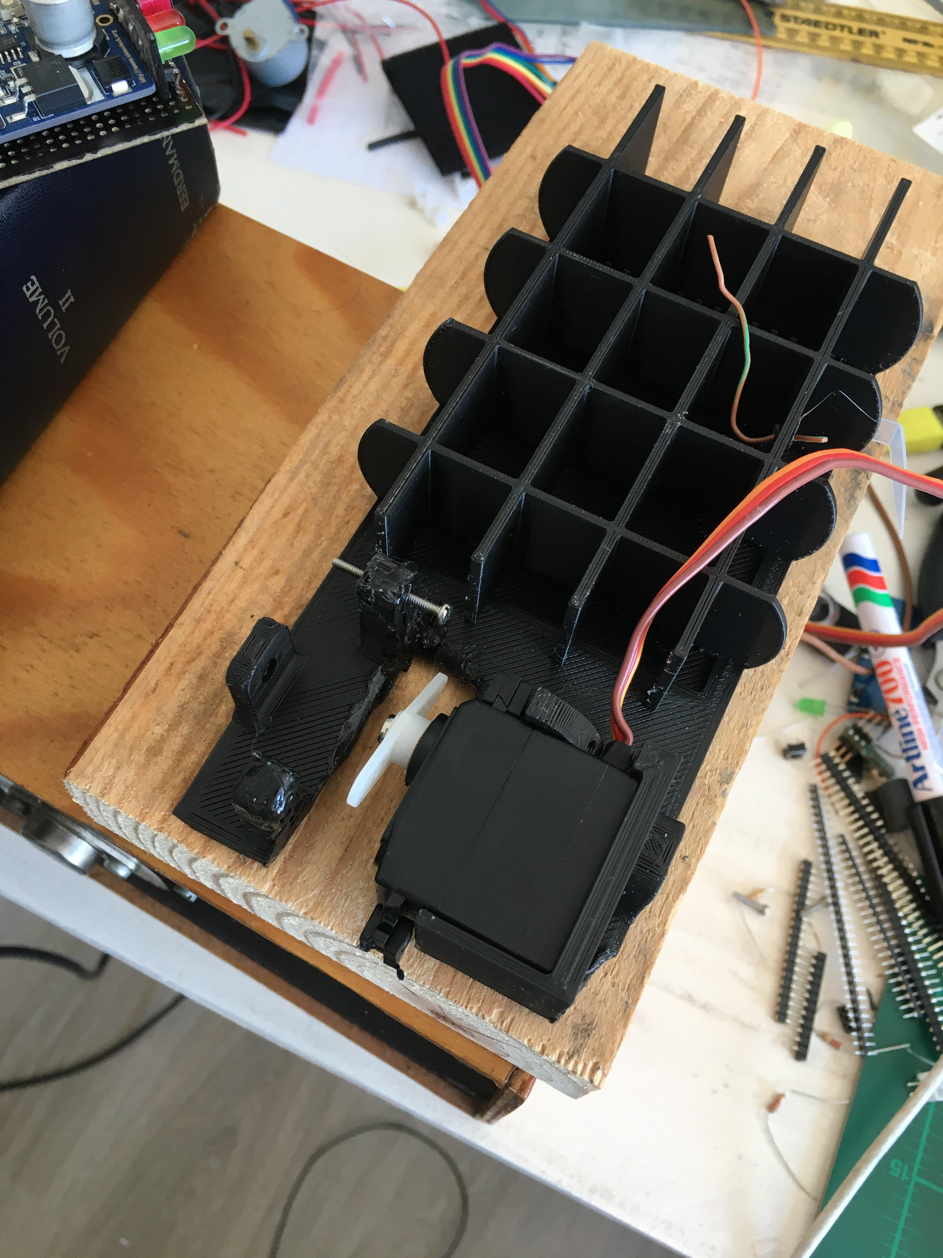
Showing how the servo fits
Attaching the servo to the hand
All set for dynamic testing
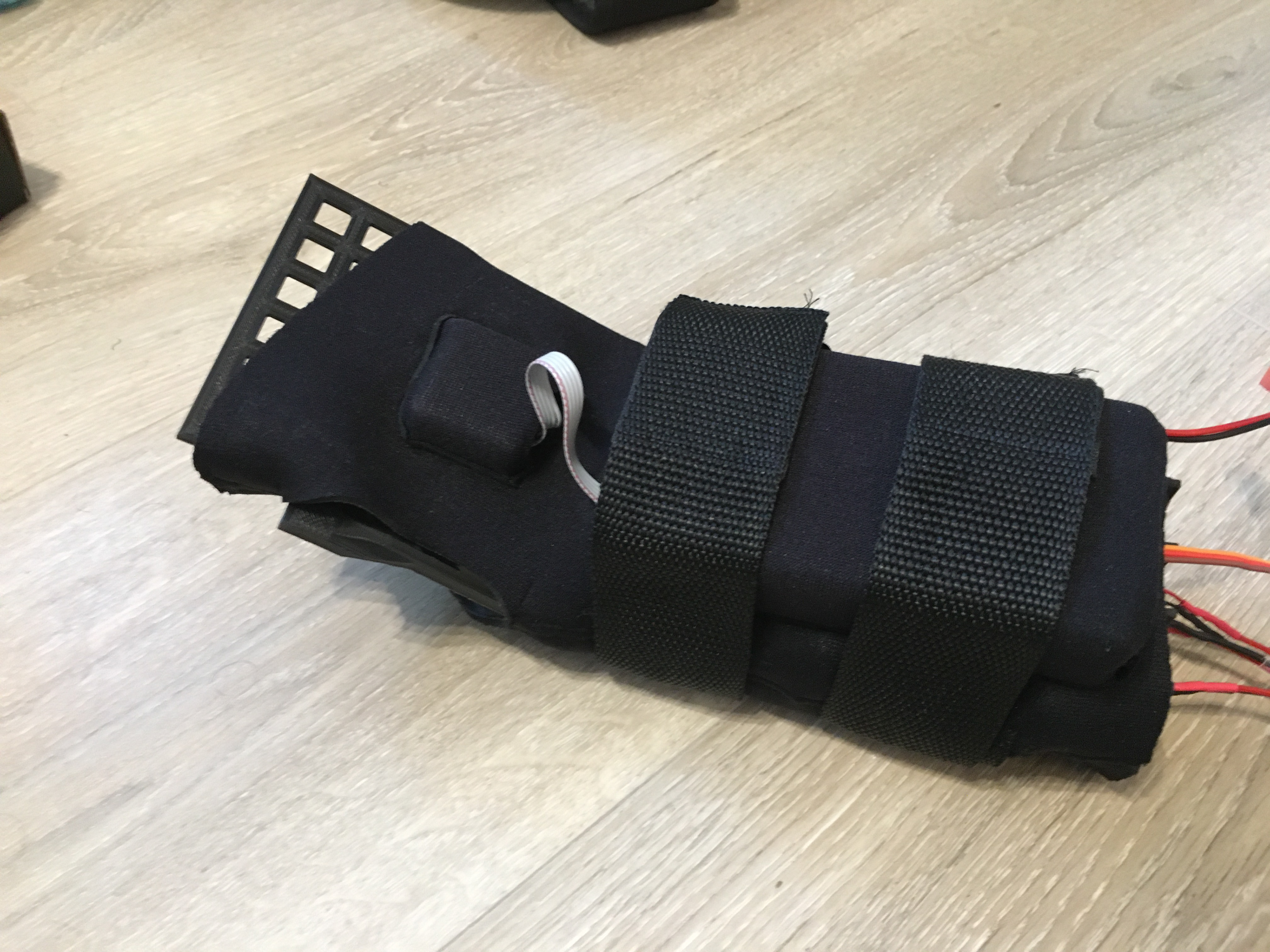
Device mounted for durability testing
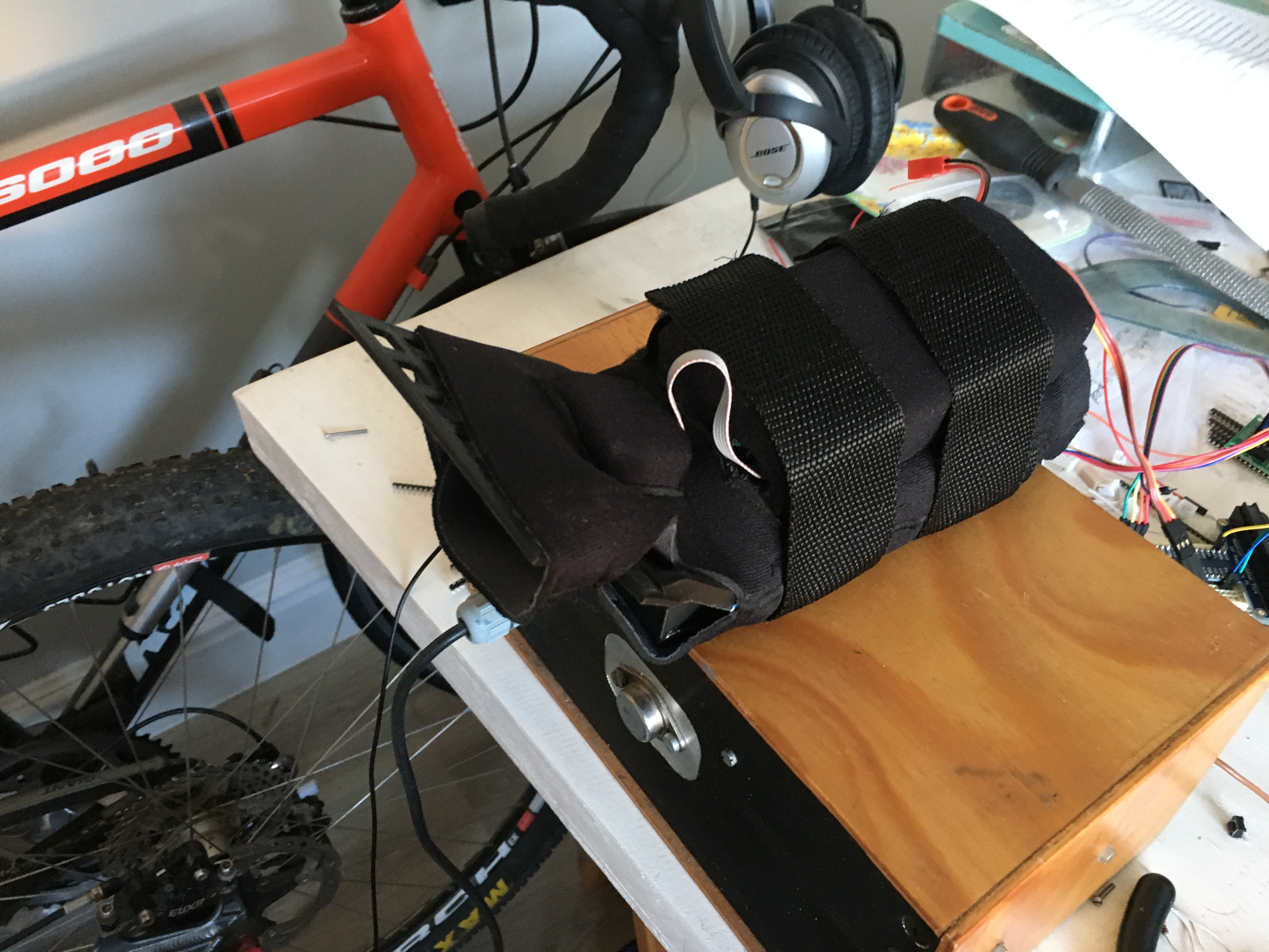
Let the wiggles begin!
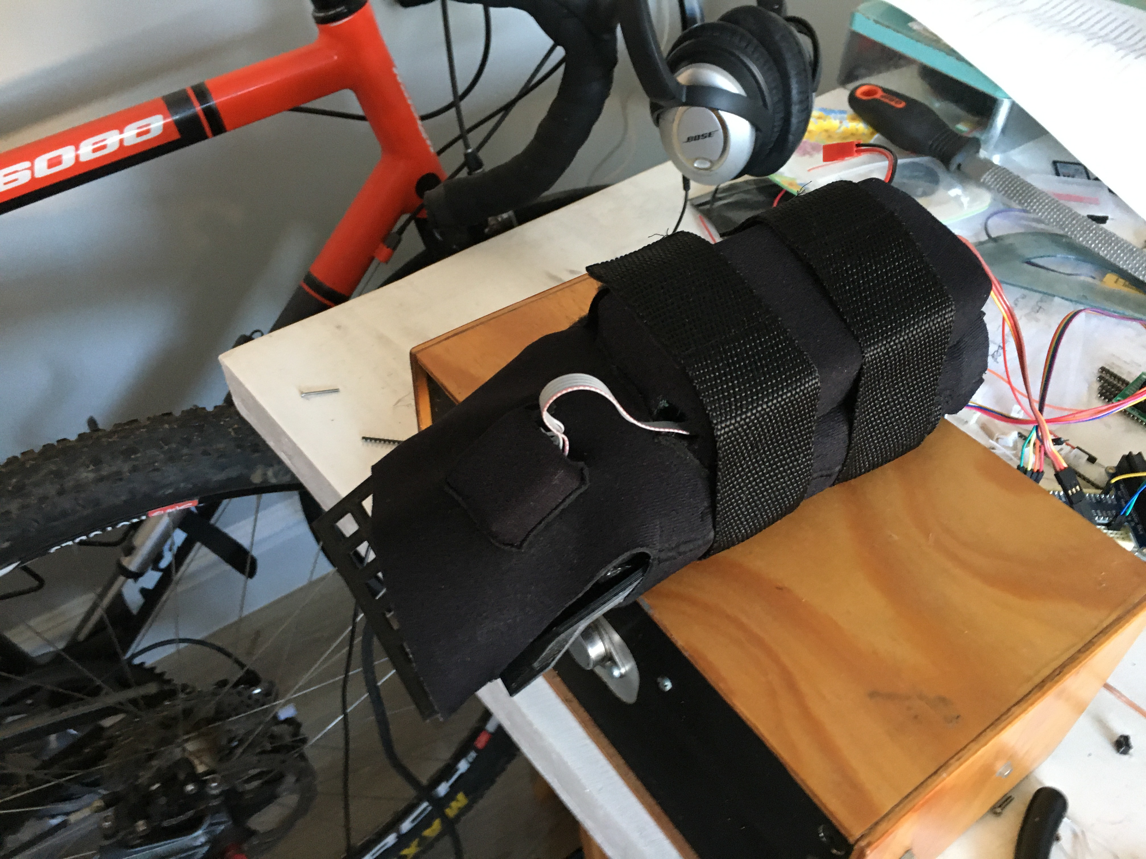
And she's off - ready for 100 000 steps...
Static Tests
Static testing involved using a stepper motor to rotate the hand relative to the arm through a specified number of degrees. The stepper motor proved not to be particularly accurate (due to play in the motor shaft, not as a result of insufficient step resolution), and so a protractor was retrofitted to the angle testing apparatus to read the angle manually. For each test set (see the various configurations above), the hand was rotated through 90 degrees up and down in 10 degree steps. The video below shows a snapshot of the process.
Rigid Dynamic Tests
In order to test the performance of the system under global dynamic rotation, the wrist angle was set to 0, 45 and 90 degrees in each test respectively, and the entire apparatus rotated through the air. the 0 degree test is illustrated in the video below.
Non-Rigid Dynamic Tests
In order to test the device's performance under movement of the hand relative to the wrist, the wrist was driven back and forth at various angles. A video camera placed perpendicularly to the protractor was used to take a frame-by-frame readout of the angle, which was compared to the data put out by the device. The below video shows the setup for the 30 degree case.
Endurance Tests
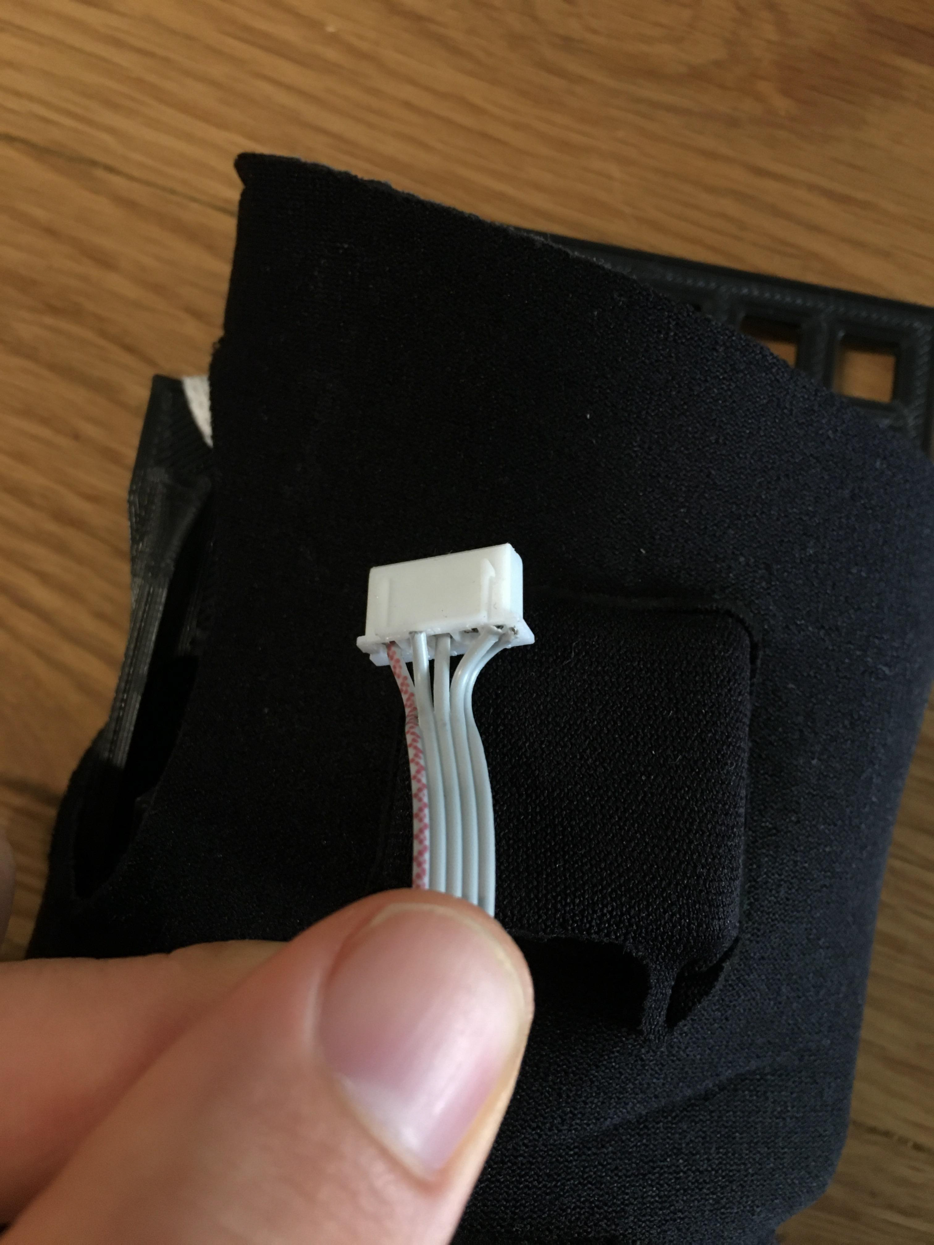
Considering the fact that the device will be worn in normal living circumstances pretty much all day for over 6 weeks, it needs to be able to take a beating. The most likely points of failure are the stitching and cabling (the neoprene is designed to last years of heavy duty ocean wear...).
In order to test these, as well as evaluate the real-world battery life of the device, the Wrist Zapper was mounted to the wrist form with the servo motor in place, and made to move back and forth through about 60 degrees for 24 hours. In this time it accomplished 100000 full reps. The battery, charged to 12V (about 80% capacity), lasted 35 hours before reaching the device warning voltage of 10.5V.
Starting durability testing
50k under the belt
100000 reps down!
The device survived durability testing mostly intact. 3 of the 5 wires in the ribbon connecting the hand IMU to the main board broke from fatigue, and the fabric outer of the neoprene sustained some wear at the point of articulation. Happily, the stitching held up!
All-in-all I am so pumped with what I've put together in this project. I love design and the design process, and it has been an absolute joy to have been able to work on such a cool device these last 3 months. God has been so, so good throughout all of it - I really would have been reduced to a puddle of stress juices by now had it not been for Jesus' relentless, incredible love.
Finally, to Jane, thank you. You have been the most wonderful supervisor. I've loved working with you, from trying to figure out relative pose estimation to considering the implications of i = die, it's been great. I really hope we'll find something to collaborate on in the future.
SDG.